Method and system for thin-wall part modal testing based on machine vision

A technology of machine vision and modal testing, which is applied in the testing of machine/structural components, testing of mechanical components, vibration testing, etc., to achieve the effects of guaranteed accuracy, high spatial resolution, and convenient operation

Active Publication Date: 2016-03-23
HUNAN UNIV OF SCI & TECH
View PDF7 Cites 30 Cited by
  • Summary
  • Abstract
  • Description
  • Claims
  • Application Information

AI Technical Summary

Problems solved by technology

[0005] In order to solve the above-mentioned technical problems existing in the modal testing of existing thin-walled parts, the present invention provides a machine vision-based thin-walled modal testing method and system with flexible devices, easy debugging, high efficiency and accuracy, and full-field non-contact , to achieve modal non-contact, full-field, high-precision measurement of thin-walled parts

Method used


Image

  • Method and system for thin-wall part modal testing based on machine vision
  • Method and system for thin-wall part modal testing based on machine vision
  • Method and system for thin-wall part modal testing based on machine vision

Examples


Embodiment Construction

[0043] The present invention will be further described below in conjunction with the accompanying drawings and specific examples.

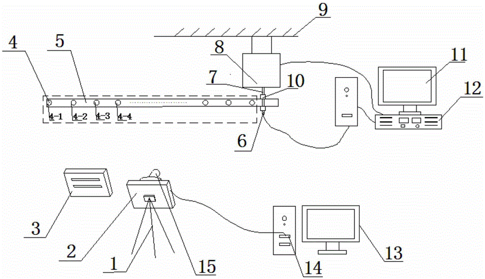
[0044] Such as figure 1 As shown, the present invention includes a tripod 1, a CCD industrial camera 2, an industrial lens 15, an ordinary LED light source 3, a reflective sticker feature point 4, a thin-walled part 5, an acceleration sensor 6, an excitation head 7, an exciter 8, a fixed Support 9, exciter control device 11, power amplifier 12, computer image processing device 13. One end of the thin-walled part 5 is fixed on the excitation head 7 through two nuts 10, and the other end is in a free suspension state. The exciter 8 is suspended on the fixed bracket 9 with a string, and the exciter 8 is connected to the power amplifier 12. , the power amplifier 12 is connected to the vibrator control device 11, an acceleration sensor 6 is installed at the end of the vibrator head 7, and is connected to the vibrator control device 11 through a data l...


PUM


Abstract

The invention discloses a method and system for thin-wall part modal testing based on machine vision. The method for the thin-wall part modal testing comprises the steps that a to-be-tested thin-wall part is fixed on an excitation head of an exciter and the to-be-tested thin-wall part is driven to perform equal-frequency vibration; meanwhile, a CCD industrial camera is used to continuously collect images of a vibration course of the thin-wall part; image processing is carried out to acquired sequence images so as to obtain an inherent frequency; the constant-frequency vibration of the thin-wall part is carried out under the inherent frequency; the continuous sequence images under the constant-frequency vibration are acquired; the image processing is carried out to the acquired continuous sequence images; and further a modal shape under the inherent frequency is obtained. The system disclosed by the invention has the advantages of a flexible structure; a complicated debugging course is not required; only low requirements are proposed for surface quality of the thin-wall part; non-contact measurement is carried out; vibration characteristics of a tested object are not changed; and the system has the advantages of high measurement precision and high efficiency, etc.

Description

technical field [0001] The invention relates to a thin-walled part modal test device, in particular to a machine vision-based thin-walled part modal test method and system. Background technique [0002] Thin-walled parts are widely used in industrial production due to their light weight and high structural efficiency. However, since the wall thickness of thin-walled parts is usually small relative to the overall size, and the general stiffness is small and the area is large, it is easy to vibrate during the operation of the mechanical system, which will cause interference between mechanical parts, vibration noise, or In the long-term movement of the machine, it will cause mechanical failure, and excessive vibration will even cause a catastrophic accident. Therefore, it is necessary to carry out modal tests on thin-walled parts. [0003] The traditional modal test method is to measure by attaching the acceleration sensor to the surface of the object to be tested. However, du...

Claims


Application Information

Patent Timeline
Patent Type & Authority Applications(China)
IPC IPC(8): G01M13/00G01M7/02G01H9/00
CPCG01H9/00G01M7/02G01M7/022G01M7/025G01M13/00
Inventor 伍济钢袁继广蒋勉龚木红李赞石海波
Owner HUNAN UNIV OF SCI & TECH
Why Eureka
Try Eureka