A device for efficient plasma transport of nuclear fusion experimental equipment

A plasma and plasma source technology, which is applied in the field of high-efficiency ion transport devices, can solve the problems of low ionization rate, low plasma beam density, plasma loss, etc., achieve good application prospects, and overcome the problems of low plasma beam density Effect

Active Publication Date: 2020-04-14
芶富均
View PDF5 Cites 0 Cited by
  • Summary
  • Abstract
  • Description
  • Claims
  • Application Information

AI Technical Summary

Problems solved by technology

Existing nuclear fusion experimental equipment only adopts a fixed-output magnetic confinement device, and the two coaxially distributed solenoid coils of the magnetic confinement device generate a magnetic field formed by the magnetic force lines along the axis of the solenoid coil to confine the plasma. In actual work, the magnetic force line will run out of the magnetic confinement device from the middle axis direction of the solenoid coil at both ends, and close the magnetic force line loop outside the magnetic confinement device, so that the plasma generated by the plasma source of the nuclear fusion experimental equipment will run out along the magnetic force line circuit. Plasma loss makes the subsequent plasma beam transported to the surface of the sample have low density and low ionization rate, which cannot meet the processing requirements of fusion materials. Moreover, during work, the operator cannot observe the ion beam bombardment of the sample at any time. It is impossible to adjust the appropriate magnetic field output strength in time according to the observed bombardment of the sample, so that the plasma beam can achieve the best output density and maximum ionization rate under the appropriate magnetic field strength

Method used


Image

  • A device for efficient plasma transport of nuclear fusion experimental equipment
  • A device for efficient plasma transport of nuclear fusion experimental equipment

Examples


Embodiment Construction

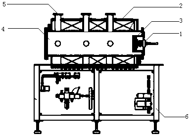
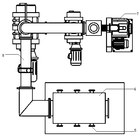
[0014] figure 1 , figure 2 As shown in , a device for efficiently transporting plasma in nuclear fusion experimental equipment, including ion source equipment 1 and magnetic field coil equipment 2 on the body of nuclear fusion experimental equipment, is composed of ion source equipment mounting plate 3 and vacuum chamber 4 , observation window 5, fixed platform 6, vacuum pump group 7, and vacuum pipeline 8. The vacuum chamber 4 is installed on the upper part of the fixed platform 6. The vacuum pump group 7 is connected to the left end of the vacuum chamber 4 through the pipeline. The ion source equipment mounting plate 3 is installed on the In the middle of the right end of the vacuum chamber 4, the ion source device 1 is installed on the right end of the ion source device mounting plate 3, and there are multiple observation windows 5, the observation window 5 is composed of a pipeline and an observation plate, the observation plate is made of transparent material, and the ob...


PUM


Abstract

A device for plasma efficient transport of nuclear fusion experimental equipment is disclosed and comprises an ion source device and a magnetic field coil device on a nuclear fusion experimental equipment body. The device for plasma efficient transport consists of an ion source device mounting plate, a vacuum chamber, observation windows, a fixed platform, a vacuum pump group and a vacuum pipeline; the vacuum chamber is installed on an upper part of the fixed platform, the vacuum pump group is connected to a left end of the vacuum chamber through the pipeline, the ion source equipment mountingplate is installed in the middle part of a right end of the vacuum chamber, the ion source device is installed on a right end of the ion source equipment mounting plate, a plurality of observation windows are arranged, each observation window consists of a pipeline and an observation plate, the observation plate is made of transparent material, the observation plate is installed on the upper partof the pipeline, pipes of the plurality of observation windows are respectively installed on a plurality of openings around an outer part of the vacuum chamber, and a plurality of magnetic field coildevices are respectively mounted around the outer part of the vacuum chamber. The device for plasma efficient transport disclosed in the invention helps overcome the shortcomings of conventional nuclear test equipment which is low in plasma beam density and ionization rate and incapable of meeting the requirements for processing fusion materials.

Description

technical field [0001] The invention relates to the field of supporting facilities used by nuclear fusion experimental equipment, in particular to a device for efficiently transporting plasma of nuclear fusion experimental equipment. Background technique [0002] At present, the global energy demand is increasing sharply. Among many new energy sources, nuclear fusion energy is considered to be one of the most potential sustainable energy sources due to its high efficiency and cleanliness. Therefore, all industrial powers in the world are now conducting continuous research on nuclear fusion. Great progress has been made. In the nuclear fusion experimental equipment, the plasma is pinched to form a beam spot with a certain diameter, and then irradiated on the sample. After the action of related facilities, the divertor on the nuclear fusion experimental equipment discharges the impurities inside the plasma, so that the sample nucleus The heat of fusion energy is released to d...

Claims


Application Information

Patent Timeline
Patent Type & Authority Patents(China)
IPC IPC(8): G21B1/05G21B1/11G21B1/17
CPCG21B1/05G21B1/11G21B1/17Y02E30/10
Inventor 芶富均
Owner 芶富均
Why Eureka
Try Eureka