A visual gastric tube implantation system

A gastric tube and catheter technology, which is applied in the field of visual gastric tube implantation system, can solve the problems of being easily strayed into the trachea, and achieve the effects of reducing patient injuries, improving market competitiveness, and reducing costs

Pending Publication Date: 2019-01-04
WUXI HOSPITAL OF CHINESE MEDICINE
View PDF0 Cites 0 Cited by
  • Summary
  • Abstract
  • Description
  • Claims
  • Application Information

AI Technical Summary

Problems solved by technology

[0003] The purpose of the present invention is to provide a visual gastric tube implantation system to solve the problem that the gastric tube is easily strayed into the trachea when it passes through the pharynx

Method used


Image

  • A visual gastric tube implantation system
  • A visual gastric tube implantation system
  • A visual gastric tube implantation system

Examples


Embodiment 1

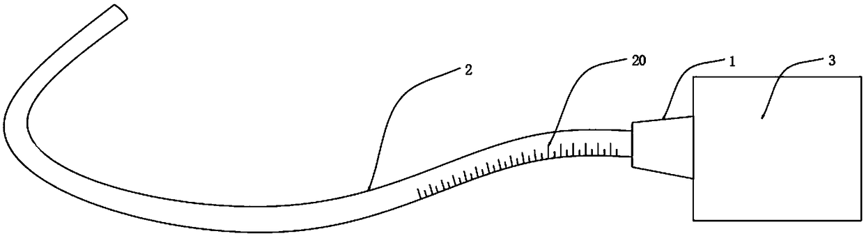
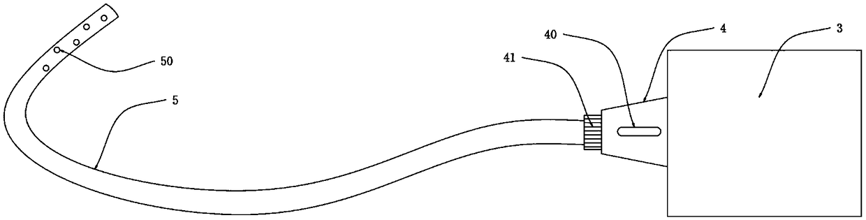
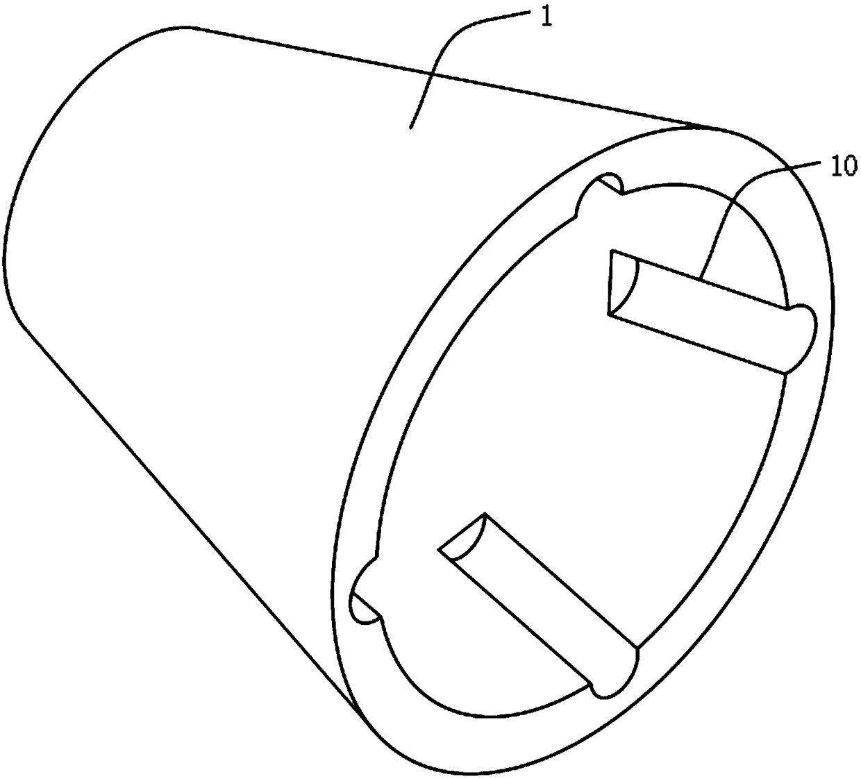
[0026] A visual gastric tube implantation system, such as figure 1 , figure 2 , image 3 with Figure 4 As shown, it includes a connector 1 and a catheter 2 arranged on one side of the connector 1. The catheter 2 and the connector 1 are fixed by glue bonding. One end of the catheter 2 is provided with an imager 3, and the catheter 2 is close to the other side. Cameras 30 are provided on the inner walls of one end, up, down, front and back, and a guide wire 5 is embedded in the catheter tube 2 .

[0027] In the present embodiment, the inner wall of the joint 1 is provided with a fixing groove 10, the left side of the imager 3 is provided with a chuck 4, and the outer wall of the chuck 4 is provided with a fixing block 40, and the bottom of the chuck 4 is left. A buckle 41 is provided on the side, and the chuck 4 is fixed in the joint 1 through the buckle 41 to improve its stability.

[0028] Further, the size of the fixing block 40 is adapted to the size of the fixing slot...

Embodiment 2

[0031] As a second embodiment of the present invention, in order to facilitate washing of the camera 30, the inventors made improvements to the inside of the distal side hole 50, as a preferred embodiment, such as Figure 5 with Image 6 As shown, a number of distal side holes 50 are provided near the end of the guide wire 5, and a drainage device 6 is embedded in the distal side hole 50. The drainage device 6 includes a fixed rod 60, and a rotating shaft 61 is provided at the bottom of the fixed rod 60. The rotating shaft 61 is provided with a drainage paddle 62, the bottom of the drainage paddle 62 is provided with a fixed plate 63, the upper surface of the fixed plate 63 is provided with an annular groove 631, and rollers 64 are provided in the annular groove 631, front, rear, left, and right.

[0032] In this embodiment, when injecting physiological saline, the drainage paddle 62 can be used to increase the flow rate of injecting physiological saline, and at the same time ...

Embodiment 3

[0037] As the third embodiment of the present invention, in order to facilitate the adjustment of the insertion depth of the gastric tube, the inventors improved the side wall of the catheter 2. On the basis of Embodiment 1, the side wall of the catheter 2 is provided with a scale Table 20. Adjusting the insertion depth of the gastric tube through image information to meet different clinical needs.

[0038] In this embodiment, both the joint 1 and the catheter 2 are made of non-toxic polyvinyl chloride material, because polyvinyl chloride has no oral mucosal irritation, no cytotoxicity, no sensitization and is sterile.

[0039] When the visualized gastric tube implantation system of the present invention is in use, at first, the catheter 2 is inserted through the nostril and then passes through the pharynx, and the end of the catheter 2 moves while the information formed on the imager 3 by the camera 30 makes the catheter 2 move. The end of the liquid tube 2 passes through the...


PUM


Abstract

The present invention relate to the field of catheter technology, in particular to a visual gastric tube implantation system, comprising a connector and a liquid guide pipe arranged on one side of theconnector. An imager is arranged at one end of the liquid guide tube, cameras are arranged on that inn walls of the upper and lower sides of the liquid guide pipe close to the other end, a liquid guide tube is embed with a guide wire, the guide wire is provided with a plurality of distal end side holes at positions close to the end portions, a distal end side hole is embedded with a drainage device. The advantages of that invention are simple structure, easy to use. By setting up the imager, the catheter can be directly inserted into the esophagus, thereby improving operational effectiveness,and reducing patient injury and ensure that the final site of the gastric tube must be the esophagus. The gastric tube insertion depth can be adjusted according to the image information to meet different clinical use requirements. The gastric tube is supported by the guide wire to ensure that the gastric tube has sufficient strength to reach the stomach. Secondly, the guide wire blockage can be effectively prevented by a drainage device, which is beneficial to repeated use after disinfection, reduces cost, and improves market competitiveness.

Description

technical field [0001] The invention relates to the technical field of catheters, in particular to a visualized gastric tube implantation system. Background technique [0002] A gastric tube is a flexible tube inserted through the nostril, through the pharynx, and through the esophagus to the stomach. It can be used to pump gastric juice or inject food into the stomach to provide the necessary nutrition for the patient. Currently, the operation of gastric tube placement is performed by nurses based on their clinical experience. Many patients cannot cooperate with clinical nurses in the operation of gastric tube placement due to their own diseases. They all open in the pharynx. When the gastric tube passes through the pharynx, it often happens that the gastric tube enters the trachea by mistake, and then the tube is pulled out and re-inserted. Multiple tube placements will damage the patient's nasal cavity, throat, airway, esophagus and other mucous membranes. Damage occurs,...

Claims


Application Information

Patent Timeline
Patent Type & Authority Applications(China)
IPC IPC(8): A61J15/00A61B1/273A61B1/04
CPCA61J15/0003A61B1/04A61B1/2733A61B1/2736
Inventor 华燕菲单珍珠周燕
Owner WUXI HOSPITAL OF CHINESE MEDICINE
Why Eureka
Try Eureka