Locking device for a motor vehicle

A technology for locking devices and motor vehicles, which is applied in the direction of electric car locks, vehicle locks, and accident locks, etc. It can solve problems such as unreliability, affecting spring performance, and large investment to achieve high functionality and high safety. Effect

Active Publication Date: 2019-03-01
KIEKERT & KOMMANDITGES
View PDF10 Cites 1 Cited by
  • Summary
  • Abstract
  • Description
  • Claims
  • Application Information

AI Technical Summary

Problems solved by technology

The defined design of the spring therefore requires a large investment
In addition, control by means of spring elements is always unreliable, since temperature fluctuations, for example, can also affect the spring behavior

Method used


Image

  • Locking device for a motor vehicle
  • Locking device for a motor vehicle
  • Locking device for a motor vehicle

Examples


Embodiment Construction

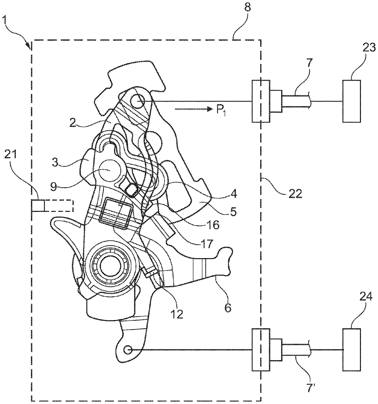
[0046] exist figure 1 A schematic diagram of a locking device 1 for a motor vehicle is shown in . The functional units 8 in the locking device 1 are only indicated by dashed lines. The functional unit 8 comprises a joystick 2 , a coupling lever 3 , a control lever 4 , an inertia lever 5 and a trigger lever 6 . For reasons of clarity, other components of the locking device 1 are not shown, so that only those components of the locking device 1 are shown to illustrate the function of the invention.

[0047] figure 1 The functional unit 8 is shown in an unactuated state. To actuate the actuation lever 2 , the actuation lever 2 is actuated in the direction of the arrow P1 , clockwise, for example by means of a Bowden cable 7 . When the actuation lever 2 is actuated, the coupling rod 3 , which is mounted in the actuation lever 2 , is possibly moved together via the shaft 9 , which mounts it in the actuation lever 2 .

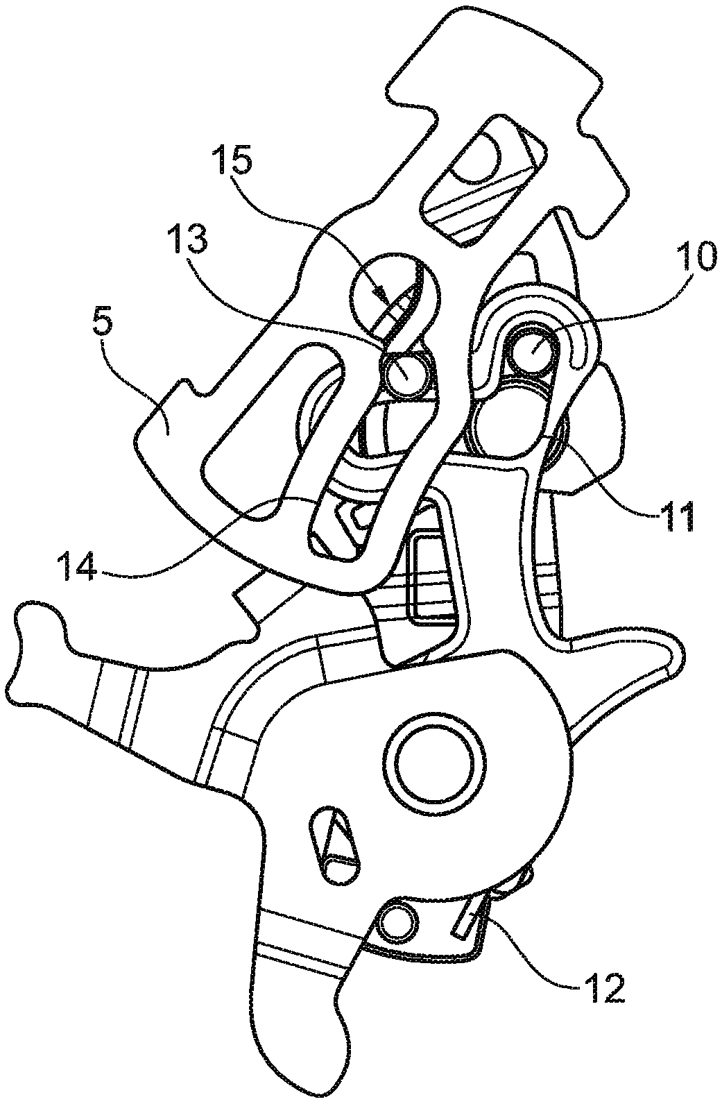
[0048] Coupling rod 3 has in turn figure 2 The more easil...


PUM


Abstract

The invention relates to a locking device (1) for a motor vehicle comprising actuating means (23), a lock (1) with a locking mechanism, comprising a rotary latch and at least one pawl, the actuating means (23) and the lock can be interconnected by means of a Bowden cable and the Bowden cable comprises means for actively blocking (8) a force transmitted by the Bowden cable (7, 7').

Description

technical field [0001] The invention relates to a locking device for a motor vehicle comprising an actuating part, in particular an outer actuating lever and / or an inner actuating lever, and a lock with a locking mechanism having a rotary locking fork and at least one locking pawl, In this case, the actuating part can be connected to the lock by means of a Bowden cable. Background technique [0002] Locks for motor vehicles, which are also referred to as locking systems, generally have a locking mechanism consisting of a rotary lock and at least one pawl. The locking mechanism in the lock cooperates here with a lock stop / bolt which is fastened either to the body of the motor vehicle or to a door, hatch, sliding door or the like. The relative movement between the lock stop and the rotary catch causes the rotary catch to pivot, while the pawl engages with the rotary catch. [0003] Depending on the embodiment there is a single-stage or two-stage locking mechanism, such that ...

Claims


Application Information

Patent Timeline
IPC IPC(8): E05B77/06E05B79/20
CPCE05B79/20E05B77/06E05B81/16
Inventor C·富赫斯
Owner KIEKERT & KOMMANDITGES
Why Eureka
Try Eureka