Optical property monitoring device based on mode coupling

A monitoring device and mode coupling technology, applied in the field of optical fiber transmission, can solve the problems of high cost and low efficiency

Pending Publication Date: 2019-04-26
NAT UNIV OF SINGAPORE SUZHOU RES INST +1
View PDF6 Cites 2 Cited by
  • Summary
  • Abstract
  • Description
  • Claims
  • Application Information

AI Technical Summary

Problems solved by technology

Traditional optical performance monitoring, such as optical signal-to-noise ratio monitoring, relies on high-speed sampling oscilloscopes to achieve optical signal-to-noise ratio monitoring by observing eye patterns, but this method is very inefficient and very expensive

Method used


Image

  • Optical property monitoring device based on mode coupling

Examples


Embodiment Construction

[0014] The following will clearly and completely describe the technical solutions in the embodiments of the present invention. Obviously, the described embodiments are only some of the embodiments of the present invention, rather than all the embodiments. Based on the embodiments of the present invention, all other embodiments obtained by persons of ordinary skill in the art without making creative efforts belong to the protection scope of the present invention.

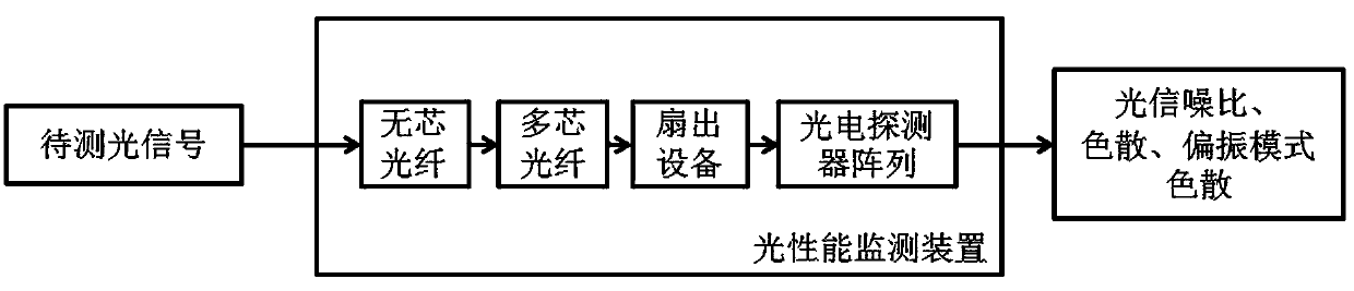
[0015] like figure 1 As shown, embodiments of the present invention include:

[0016] An optical performance monitoring device based on mode coupling, comprising a coreless optical fiber, a multi-core optical fiber, a fan-out device and a plurality of photodetectors, the input end of the coreless optical fiber is connected to an optical input signal, and the output end of the coreless optical fiber is connected to multiple The input end of the core optical fiber, the output end of the multi-core optical fiber is con...


PUM


Abstract

The invention discloses an optical property monitoring device based on mode coupling, which comprises a coreless optical fiber, a multi-core optical fiber, fan-out equipment and a plurality of photoelectric detectors. The input end of the coreless optical fiber is connected with an optical input signal; the output end of the coreless optical fiber is connected with the input end of the multi-coreoptical fiber; the output end of the multi-core optical fiber is connected with the fan-out equipment; the output end of the fan-out equipment is connected with the plurality of photoelectric detectors; the number of the photoelectric detectors is kept consistent with the number of fiber cores of the multi-core optical fibers. From the above, the optical property monitoring device based on mode coupling, which is disclosed by the invention, implements monitoring on optical properties of the received optical signal, which include an optical signal-to-noise ratio, dispersion, polarization modedispersion and the like, in cases of not modifying a sender and not influencing data transmission.

Description

technical field [0001] The invention relates to the technical field of optical fiber transmission technology, in particular to an optical performance monitoring device based on mode coupling. Background technique [0002] With the development of Internet technology, such as high-definition live broadcast, virtual reality, cloud computing, etc., the amount of communication data in optical fiber systems is increasing day by day. In order to meet the requirements of the explosive growth of Internet communication data volume, high-speed dynamic reconfigurable optical communication network technology has received great attention. Among them, it is of great significance to realize real-time optical performance detection of high-speed dynamic reconfigurable optical network. The optical communication system performance test detects the transmission status of the physical layer of the optical network by directly measuring the damage parameters of the optical signal after transmissio...

Claims


Application Information

Patent Timeline
Patent Type & Authority Applications(China)
IPC IPC(8): H04B10/079
CPCH04B10/0795
Inventor 李焱徐伟徐卓然余长源
Owner NAT UNIV OF SINGAPORE SUZHOU RES INST
Why Eureka
Try Eureka