Dispersion real-time monitoring method applied in DWDM high speed transmission system

A high-speed transmission and real-time monitoring technology, applied in the field of dispersion management, can solve the problems of incorrect monitoring of dispersion, incorrect transmission of information, and inability to apply communication systems, etc., to achieve long monitoring distance, easy application, and high measurement accuracy Effect

Inactive Publication Date: 2007-02-14
UNIV OF ELECTRONICS SCI & TECH OF CHINA +1
View PDF0 Cites 8 Cited by
  • Summary
  • Abstract
  • Description
  • Claims
  • Application Information

AI Technical Summary

Problems solved by technology

[0005] (1) The monitoring signal cannot correctly monitor the dispersion due to the interference of the data signal;
[0006] (2) The data signal cannot transmit information correctly due to the interference of the monitoring signal
[0007] Therefore, the practice of putting the monitoring signal and the data signal in one channel cannot be applied to the actual communication system

Method used


Image

  • Dispersion real-time monitoring method applied in DWDM high speed transmission system
  • Dispersion real-time monitoring method applied in DWDM high speed transmission system
  • Dispersion real-time monitoring method applied in DWDM high speed transmission system

Examples


Embodiment Construction

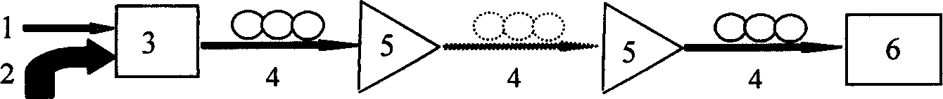
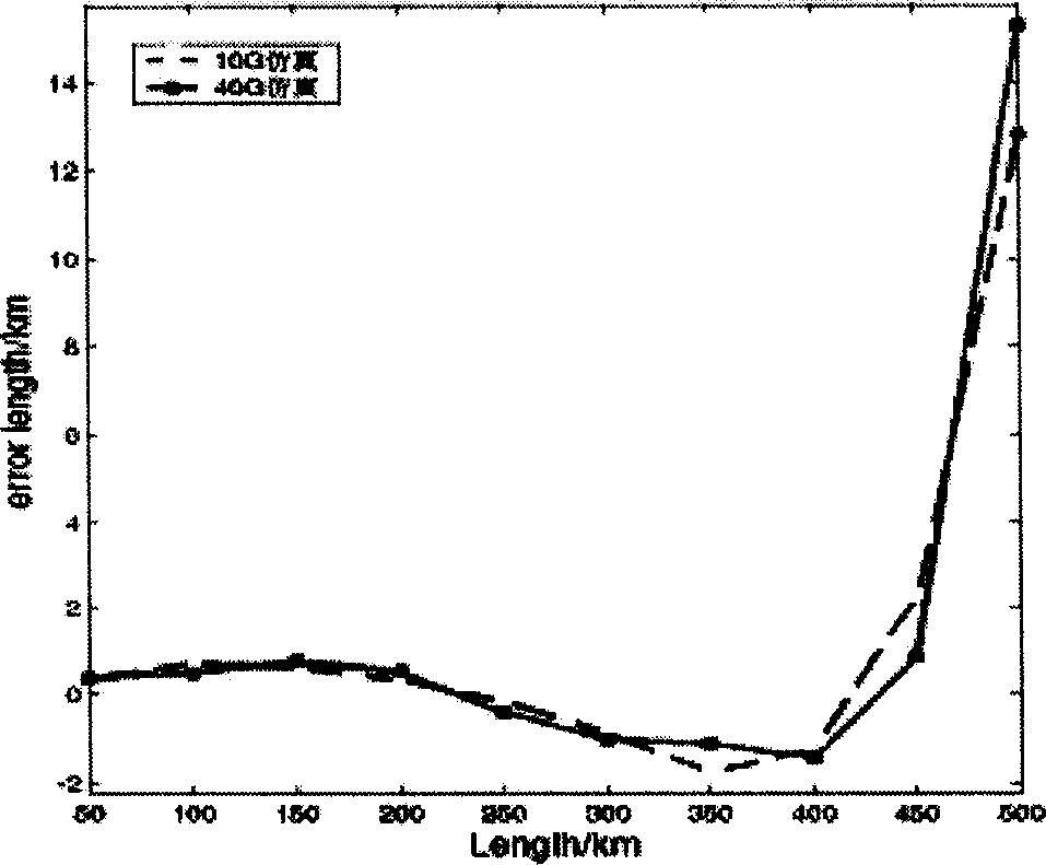
[0037] We have carried on the emulation of the DWDM system of n = 16 channels. In the simulation, the center wavelength of the monitoring channel is 1558.58nm, and the center wavelength interval of 16 channels is 0.8nm. Considering the nonlinear effect of optical fiber, the frequency of the monitoring signal for phase modulation is 2.5GHz. The transmission fiber is a standard single-mode G.652 fiber, and the relay distance is 50km. The gain of the optical amplifier is 10dB, the central wavelength of the optical filter of the monitoring channel is 1558.58nm, and the 3dB bandwidth is 40GHz. The error curve between the monitoring value and the theoretical calculation value of the monitoring signal transmitted through the 500km standard single-mode fiber is as follows: figure 2 shown. It can be seen from the results that the 10Gbit / s and 40Gbit / s systems have the largest measurement errors of 12.8km and 15.3km respectively at 500km. In a 10Gbit / s optical fiber transmission sy...


PUM


Abstract

This invention provides a method for monitoring fiber dispersion timely in the high speed DWDM system, which applies a method that a monitor signal occupies a channel independently while the original network topological structure is not changed to avoid influence of digital signals in the traditional method to monitor signals, which can monitor the dispersion volume of each channel accurately and carry out dynamic optical routing on the optical path to provide a very good management plan to dispersion to the intelligent optical network wide of the next generation.

Description

Technical field [0001] The invention belongs to the technical field of optical fiber communication, and in particular relates to the dispersion management technology in a Dense Wavelength Division Multiplexing (DWDM) system. Background technique [0002] The signal is carried by different frequency components and different mode components in the optical fiber. These different frequency components and modes have different propagation speeds when passing through the same material, thus causing dispersion. It can also be understood from the perspective of the broadening of the waveform in time, that is, when the optical pulse propagates through the optical fiber, its waveform is broadened in time and causes signal distortion and distortion. This phenomenon is called dispersion. Since the 1890s, the development of Internet networks has led to the rapid growth of data communication services, and customers have increasingly demanding optical fiber communication capacity. At prese...

Claims


Application Information

Patent Timeline
Patent Type & Authority Applications(China)
IPC IPC(8): H04B10/08H04B10/18H04J14/02H04B10/071H04B10/2525
Inventor 陈福深郑光金李纯丹周伟勤
Owner UNIV OF ELECTRONICS SCI & TECH OF CHINA
Why Eureka
Try Eureka