Coriolis flowmeter

a flowmeter and coriolis technology, applied in the field of coriolis flowmeters, can solve the problems of not particularly remarkable improvement in sensitivity, and achieve the effect of reducing the influence of extraneous vibration

Active Publication Date: 2007-02-15
NAT INST OF ADVANCED IND SCI & TECH
View PDF3 Cites 109 Cited by
  • Summary
  • Abstract
  • Description
  • Claims
  • Application Information

AI Technical Summary

Benefits of technology

[0090] Further, according to another aspect of the present invention, in the above-mentioned Coriolis flowmeter, the Coriolis flowmeter further includes two vibration amplitude detecting means for detecting the vibration amplitude of the Coriolis vibration generated by the Coriolis force generated by the forced vibration, the two vibration amplitude detecting means are arranged to be capable of effectively removing the vibration component of the forced vibration, a noise vibration from outside, and vibrations other than the rotational vibration of the vibration axis of the Coriolis vibration, the vibration amplitude of the vibration around the vibration axis of the Coriolis vibration being obtained by obtaining a differential signal of the two vibration amplitude detecting means, the Coriolis flowmeter further includes two vibration amplitude detecting means for detecting the vibration amplitude of the forced vibration means, and the two vibration amplitude

Problems solved by technology

However, no particularly remarkable improvement has beenmade regarding sensitivity (more preci

Method used


Image

  • Coriolis flowmeter
  • Coriolis flowmeter
  • Coriolis flowmeter

Examples


first embodiment

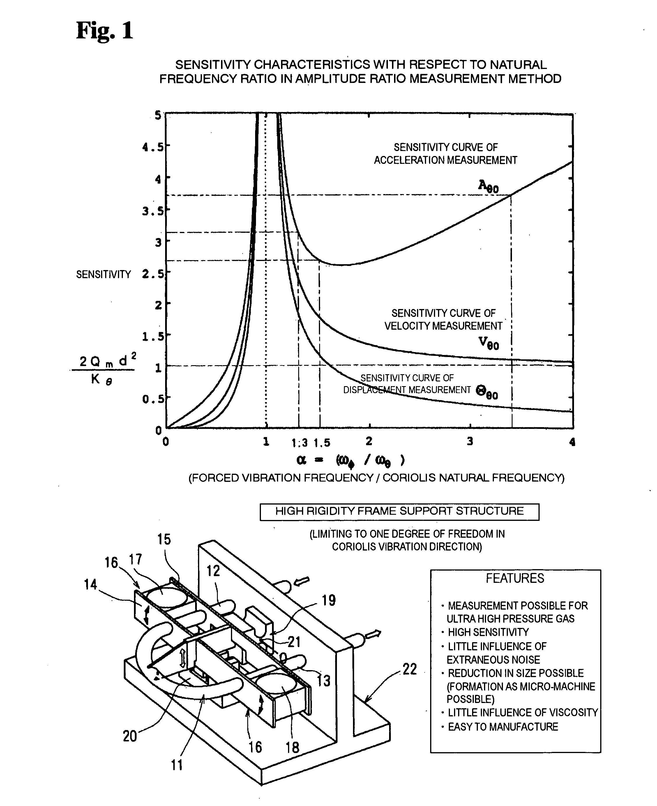
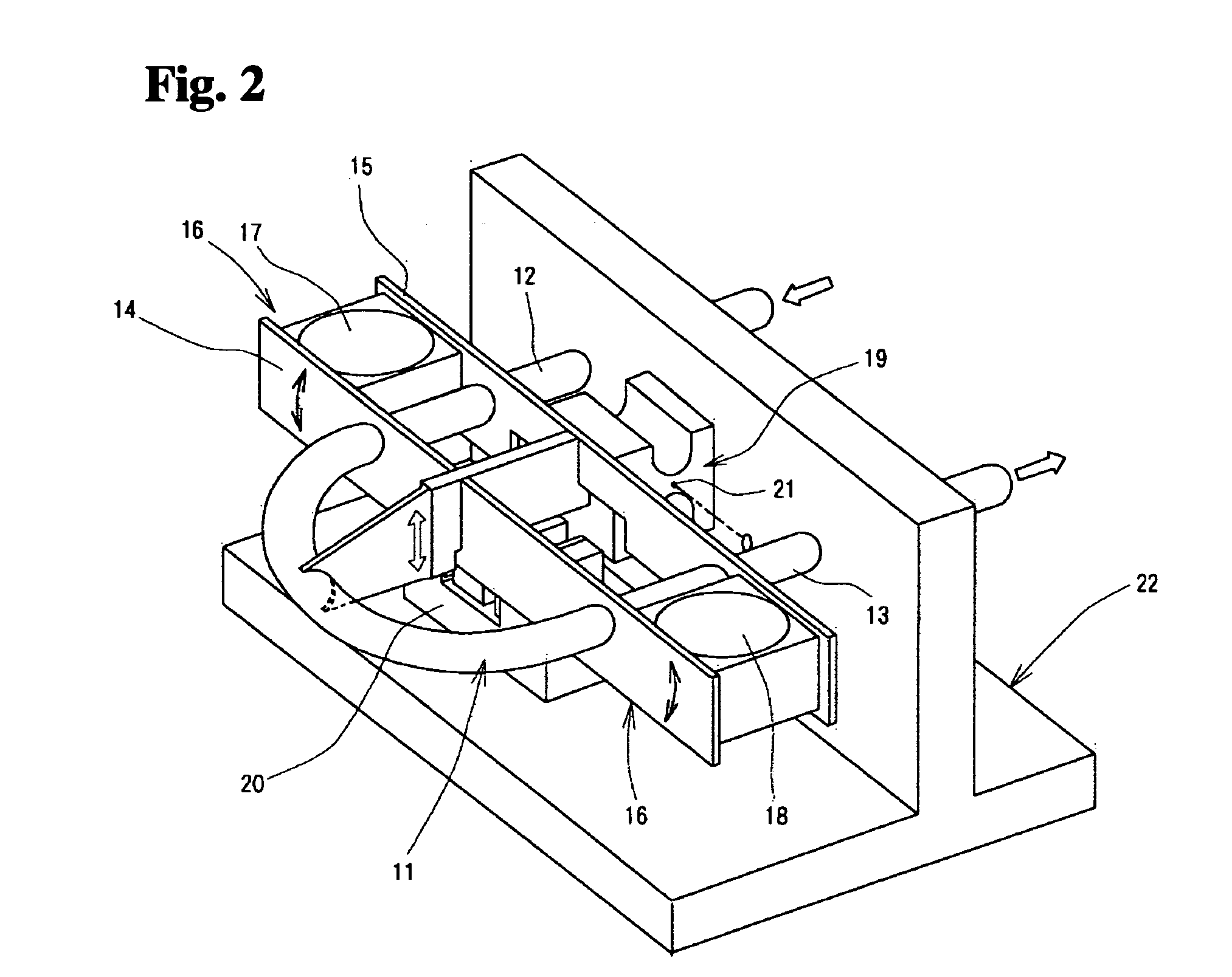
[0109] In the following, embodiments of the present invention based on the basic idea as described above will be described. FIG. 2 shows the present invention. A U-shaped tube 11 has straight pipe portions 12 and 13, which are supported by a Coriolis vibration frame 16 composed of two parallel reinforcing plates 14 and 15, and acceleration sensors 17 and 18 are fixed to the end portions of the vibration frame 16 to be situated between the reinforcing plates 14 and 15. Instead of the acceleration sensors 14 and 15, it is also possible to use velocity sensors. Further, a forced vibration frame 19 supporting the Coriolis vibration frame 16 to allow vibration is fixed to the middle portion of the reinforcing plates 14 and 15 and at a central position between the straight pipe portions 12 and 13 of the U-shaped tube, that is, at the torsional center of the U-shaped tube 11.

[0110] In this device, the Coriolis vibration frame 16, which is composed of the reinforcing plates 14 and 15 for ef...

second embodiment

[0122]FIG. 3 shows a straight type Coriolis flowmeter according to the present invention. Through a variation in the piping wall thickness, this flowmeter is divided into a bending portion that can be easily deformed and a frame portion that may be substantially regarded as a rigid frame.

[0123] A Coriolis vibration portion 25 at the center is formed as a thin-walled portion so that it can swing through Coriolis vibration. A support member 27 made capable of swinging there causes it to vibrate at a frequency higher than the Coriolis frequency. As a result, the pipes on the right-hand and left-hand sides are caused to vibrate vertically. This is based on the same principle as the conventionally used straight type Coriolis flowmeter shown in FIG. 12. However, due to the provision of the bending portion and the frame portion, a higher-mode vibration is not easily generated if excited at a frequency higher than the natural frequency of the piping or the natural frequency of the vibration...

third embodiment

[0126]FIG. 4 shows a Coriolis flowmeter composed of a so-called B-shaped sensor tube according to the present invention. Although similar in appearance to the one as disclosed in JP 2-5010006 A, this flowmeter differs therefrom in the direction in which the forced vibration is effected.

[0127] In the Coriolis flowmeter shown in FIG. 4, substantially the central portion of a longitudinal frame 35 is fixed to a swing support 34 fixed to a base 33, and a first lateral frame 36 extending perpendicularly to the longitudinal frame 35 is fixed to an end portion of the longitudinal frame 35 and a second lateral frame 39 supporting a first outer straight pipe 37 and a second outer straight pipe 38 is fixed to the other end portion of the longitudinal frame 35. Further, fixed in position be tween the first lateral frame 36 and the second lateral frame 39 is a third lateral frame 42 supporting a first inner straight pipe 40 and a second inner straight pipe 41. Further, in the example shown, the...


PUM


Abstract

When outputs from two vibration detection sensors are measured by a Coriolis flowmeter in a form of phase difference time, a tube must be thinned to increase a sensitivity of the flowmeter to enable measurement and accordingly flow velocity and pressure loss increase, and a thickness of the flowmeter must be reduced and therefore a pressure resistance cannot be readily enhanced. In particular, the sensitivity of signals to flow rate is difficult to increase and, accordingly, a flow rate of a low-density gas cannot be accurately measured. In the present invention, a Coriolis vibration frame 16 carrying a U-shaped tube is swingably fixed to a forced vibration frame 19 fixed to a support base 22 to form a highly rigid frame structure limiting a vibrating direction to one degree of freedom in a Coriolis vibration direction. The forced vibration frame 19 is vibrated by a vibration exciter 20 so that a ratio of a forced vibration frequency to the Coriolis frequency of a pipeline is at least 1 to 10. The ratio of the amplitude of the forced vibration to the amplitude of the Coriolis vibration is calculated based on signals from two vibration sensors such as acceleration sensors 17 and 18 to measure the mass flow rate of a fluid flowing in the pipeline.

Description

TECHNICAL FIELD [0001] The present invention relates to a Coriolis flowmeter for measuring a mass flow rate of a fluid by detecting a torsional vibration due to a Coriolis force generated in the fluid in a vibrating flow path, in particular, a Coriolis flowmeter capable of performing the measurement of the mass flow rate on an ultra-high-pressure gas, a low density fluid, etc. with enhanced accuracy. BACKGROUND ART [0002] A Coriolis flowmeter has conventionally been used as a flowmeter for directly measuring the mass flow rate. When a fluid flowing through piping makes a rotational motion, the fluid receives a Coriolis force, which is in proportion to the vector product of the velocity vector of the flow and the angular velocity vector of the rotation. The Coriolis flowmeter measures the mass flow rate of the fluid by detecting, by some method or other, an elastic deformation of the piping generated by this inertial force. [0003] The Coriolis flowmeter is a direct type mass flowmete...

Claims


Application Information

Patent Timeline
IPC IPC(8): G01F1/84
CPCG01F1/8409G01F1/8413G01F1/8418G01F1/8422G01F1/849G01F1/8431G01F1/8472G01F1/8486G01F1/8427
Inventor DOIHARA, RYOJITAKAMOTO, MASAKITERAO, YOSHIYA
Owner NAT INST OF ADVANCED IND SCI & TECH
Why Eureka
Try Eureka