Method for Generating Energy in an Energy Generating Installation Having a Gas Turbine, and Energy Generating Installation Useful for Carrying Out the Method

a technology of energy generating installation and gas turbine, which is applied in the direction of machines/engines, mechanical equipment, separation processes, etc., can solve the problems of reducing efficiency, limiting the future, and reducing the emissions of power stations, so as to achieve the effect of efficient removal of carbon dioxide without appreciable efficiency loss

Inactive Publication Date: 2008-01-17
ALSTOM TECH LTD
View PDF7 Cites 254 Cited by
  • Summary
  • Abstract
  • Description
  • Claims
  • Application Information

AI Technical Summary

Benefits of technology

[0018] One of numerous aspects of the present invention includes providing a method for generating energy, based on a gas turbine cyclic process, and an ene

Problems solved by technology

For this reason, international agencies and local governments are at the present time deliberating on the set-up of emission systems and will possibly introduce limitations on the future CO2 emissions of power stations.
Each of these ways, however, has disadvantages which are reflected in a reduction in efficiency, in an increase in capital costs for the power station, or in necessary co

Method used


Image

  • Method for Generating Energy in an Energy Generating Installation Having a Gas Turbine, and Energy Generating Installation Useful for Carrying Out the Method
  • Method for Generating Energy in an Energy Generating Installation Having a Gas Turbine, and Energy Generating Installation Useful for Carrying Out the Method
  • Method for Generating Energy in an Energy Generating Installation Having a Gas Turbine, and Energy Generating Installation Useful for Carrying Out the Method

Examples


Embodiment Construction

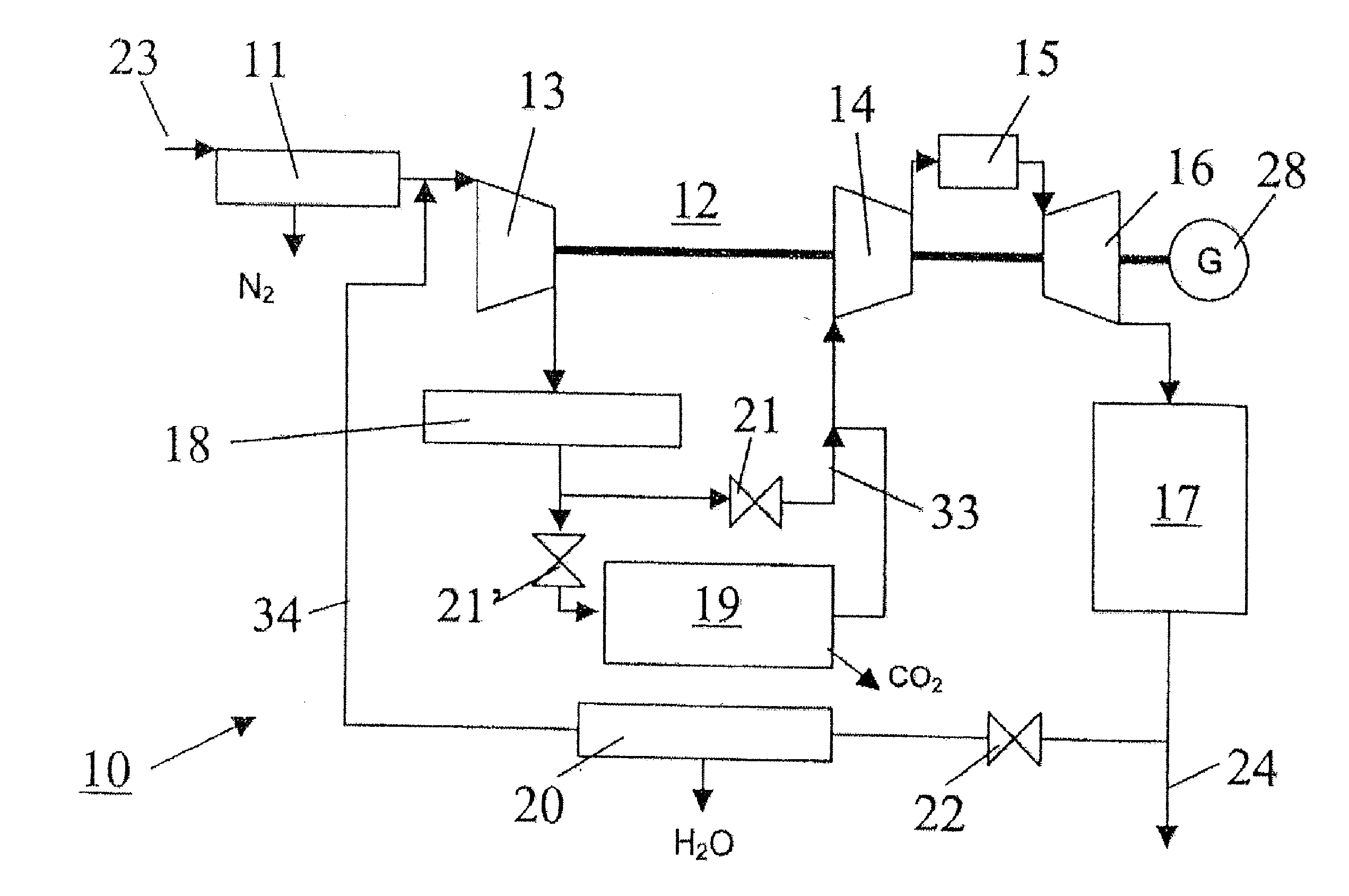
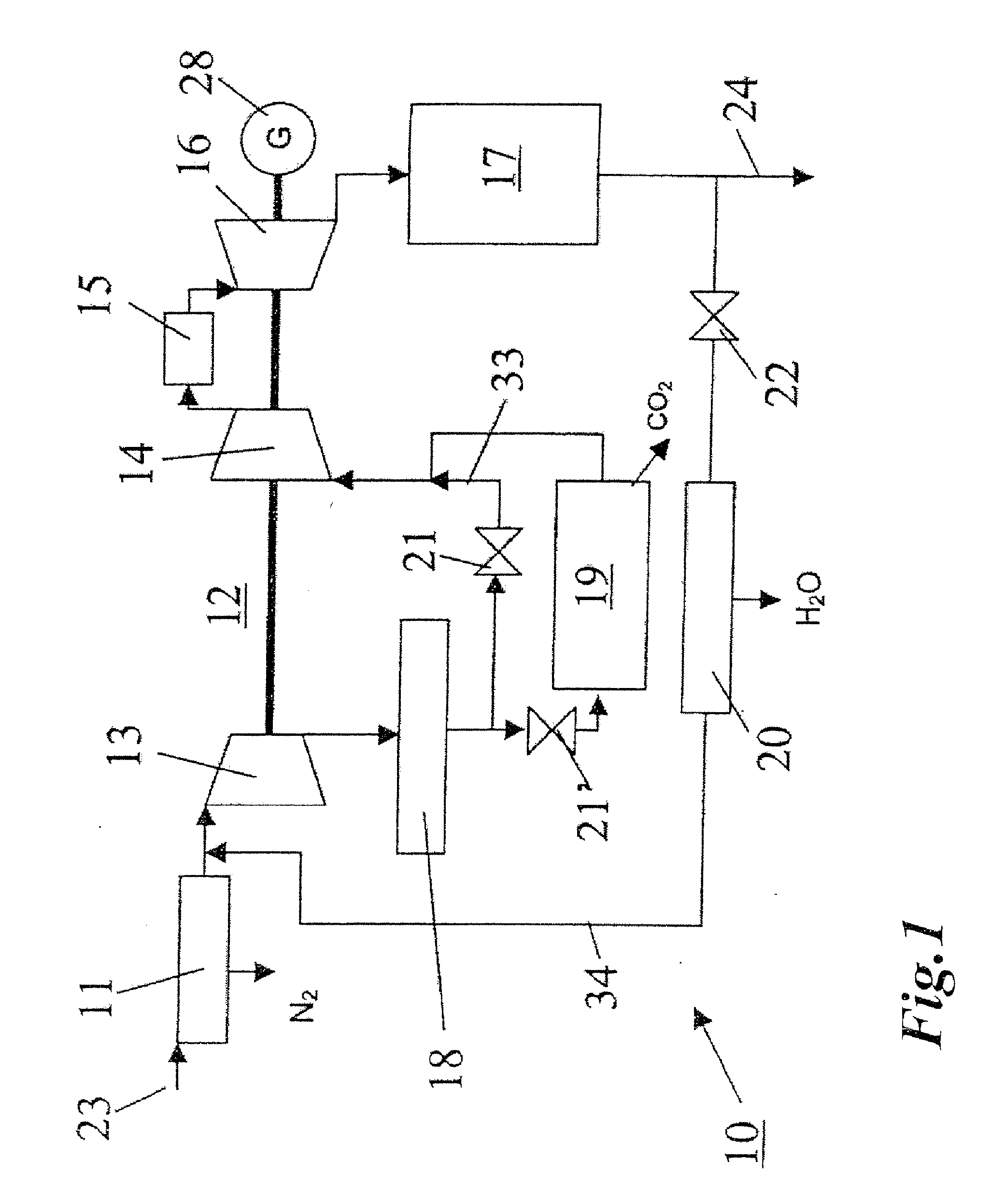
[0039]FIG. 1 reproduces a simplified installation diagram of an energy generating installation 10 according to a first exemplary embodiment of the invention. The energy generating installation 10 includes a gas turbine 12 with two compressor stages 13 and 14 connected in series, with a combustion chamber 15 and with a turbine 16 which drives a generator 28. The compressor stages 13, 14 and turbine 16 are seated on a common shaft in the usual way. Of course, the compressor stages and the turbine may also be arranged on a plurality of shafts, in which case the turbine may additionally be subdivided likewise into two or more stages. The first compressor stage 13 sucks in air 23 which, before compression, is enriched with oxygen by the extraction of nitrogen N2 in an oxygen enrichment device 11. Flue gas recirculated from the outlet of the installation is admixed to the air, optionally enriched with oxygen. The resulting gas enriched with oxygen is precompressed in the first compressor ...


PUM


Abstract

In a method for generating energy in an energy generating installation (10) having a gas turbine (12), in a first step, an oxygen-containing gas is compressed in a compressor (13, 14) of the gas turbine (12), in a second step the compressed gas is supplied, with the addition of fuel, for combustion in a combustion chamber (15), in a third step the hot flue gas from the combustion chamber (15) is expanded in a turbine (16) of the gas turbine (12) so as to perform work, and, in a fourth step, a branched-off part stream of the expanded flue gas is recirculated into a part of the gas turbine (12) lying upstream of the combustion chamber (15) and is compressed. A reduction in the CO2 emission, along with minimal losses of efficiency, is achieved in that carbon dioxide (CO2) is separated from the circulating gas in a CO2 separator (19), and in that measures are taken to compensate for the efficiency losses in the gas turbine cyclic process which are associated with the CO2 separation.

Description

[0001] This application is a Continuation of, and claims priority under 35 U.S.C. § 120 to, International application number PCT / EP2005 / 053838, filed 4 Aug. 2005, and claims priority therethrough under 35 U.S.C. § 119 to German application number 10 2004 039 164.5, filed on 11 Aug. 2004, the entireties of which are incorporated by reference herein. BACKGROUND OF THE INVENTION [0002] 1. Field of the Invention [0003] The present invention relates to the field of energy generating technology. It refers to a method for generating energy in an energy generating installation having a gas turbine, and to an energy generating installation useful for carrying out the method. [0004] 2. Brief Description of the Related Art [0005] On account of their wide availability and their low price, fossil fuels are forecasted to remain the main energy source for power generation for the next 20 to 50 years. The demand for electrical energy will increase during this period at about 2-3% per year. At the s...

Claims


Application Information

Patent Timeline
IPC IPC(8): F02C3/00
CPCB01D53/22Y02E20/16F02C3/34
Inventor GRIFFIN, TIMOTHYBUECKER, DOMINIKUSABBOTT, DAVID JOHN
Owner ALSTOM TECH LTD
Why Eureka
Try Eureka