Test element analysis system

a technology of element analysis and test element, applied in the field of test element analysis system, can solve the problems of high risk of contamination of measuring device, inability to always be possible, and inability to optimally handle the measurement, and achieve the effect of easy handling and high measurement accuracy

Inactive Publication Date: 2007-08-28
ROCHE DIAGNOSTICS GMBH
View PDF20 Cites 118 Cited by
  • Summary
  • Abstract
  • Description
  • Claims
  • Application Information

AI Technical Summary

Benefits of technology

[0006]On this basis, the invention addresses the problem of providing a photometrical test element analysis system which allows a high measurement accuracy and simultaneously an easy handling.
[0011]In order to effect the desired coupling out of the light from the light guide layer into the detection zone of the test field in the coupling out zone, different means can be used which will be explained further below. In particular, by appropriate means, the refraction index adjacent the boundary surface of the light guide layer in the coupling out zone is adapted to be not lower, or only a little lower, than the refraction index of the light guide layer, so that total reflection does not, or only to a very low extent take place here. The coupling out can also be supported by roughening the surface of the light guide layer in the coupling out zone. Furthermore, the coupling out of the light can be effected by an appropriate light guidance of the light in the guide layer, such that at least a large share of the primary light in the coupling out zone is incident onto the boundary surface directed towards the test field with an angle which is larger than the limiting angle αc of the total reflection (sin αc=n1 / n2). This can be achieved, in particular, by making the flat side of the light guide layer, opposite to the coupling out zone, inclined, at least in sections, in such a manner that the primary light is reflected into the detection zone.
[0012]The secondary light which is diffusely reflected from the detection zone is reflected into the light guide layer and is transported therein for at least a part of the way to the detector, preferably under total reflection conditions. Basically, it is possible to transport the primary light and the secondary light in a single-layer carrier film, i.e. in the same light guide layer. However, an embodiment is preferred in which the carrier film comprises two light guide layers in order to transport the primary light and the secondary light separately. By appropriate measures, to be explained further below, it can be achieved that the light captured by the detector is essentially free from interfering primary light proportions. Thereby a very good signal / noise-ratio is obtained.

Problems solved by technology

The handling during measurement is, however, not optimal.
In particular, there is a high risk of contamination of the measuring device.
This is however not always possible, in particular because diabetics are a very important group of test element analysis system users, and in many cases these patients have, due to their advanced age and their restricted eyesight, difficulties in bringing a blood drop, generated by a puncture in their finger, onto the test field accurately and without contamination of the surrounding areas.
Such contamination can lead to a dirt accumulation on the optical measuring system which drastically reduces the accuracy of subsequent measurements.
Furthermore, the cleaning of contaminated device parts is unpleasant.
In some application cases, such contamination may even cause a danger of infection.

Method used


Image

  • Test element analysis system
  • Test element analysis system
  • Test element analysis system

Examples


Embodiment Construction

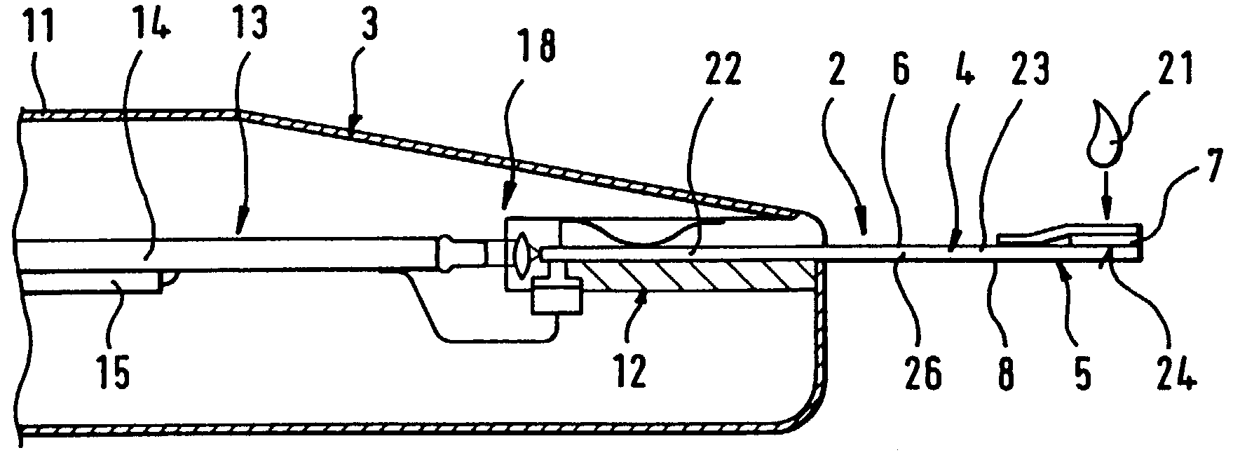
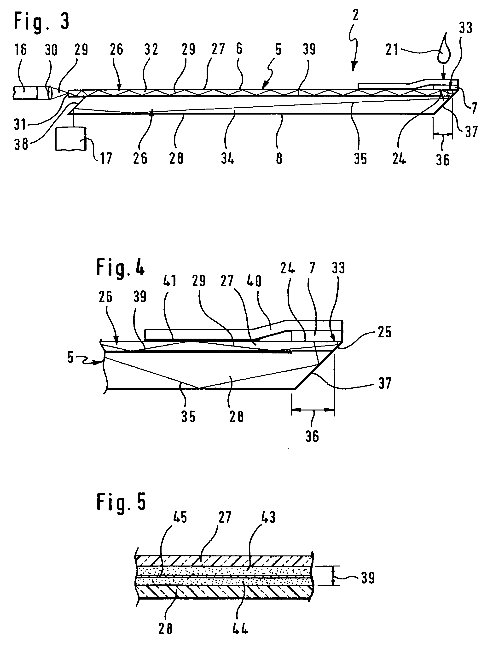
[0031]The carrier film of the invention comprises preferably, as shown in the FIGS. 3 and 4, two light guide layers 26, the upper light guide layer serving as primary light guide and the lower light guide layer serving as secondary light guide. The primary light 29 is coupled by the light emitter 16 and a lens 30 into the primary light guide 27 through its rear face serving as entrance surface 31 for the coupling in, and is transported inside the primary light guide 27 to the test field 7. The part of the light path of the primary light 29 which is inside the light guide layer 26, is designated light guide section 32. The zone of the upper flat side 6 of the light guide layer 26, which is in line with the test field, serves, at least partially, as coupling out zone 33, where the primary light 29 is coupled out of the light guide layer 27 into the detection zone 24 of the test field 7.

[0032]In the embodiment shown, the coupling out of the primary light is essentially effected by the ...


PUM

PropertyMeasurementUnit
thicknessaaaaaaaaaa
thicknessaaaaaaaaaa
widthaaaaaaaaaa

Abstract

Test element analysis system for the analytical investigation of a sample, in particular of a body liquid of human beings or animals, comprising test elements (2) with a carrier film (5) and a test field (7) fixed to the flat side (6) of the carrier film (5), the test field (7) containing a reagent system the reaction of which with the sample (21) leads to an optically measurable change in the detection zone (24) which is characteristic for the analysis, and an evaluation instrument with a measuring device for measuring the optically measurable change. In order to obtain a very high measuring accuracy and an easy handling at the same time, the carrier film (5) of the test element (2) comprises a light guide layer (26), the detection zone (24) of the test field (7) is in optical contact to the light guide layer (26) in a coupling out zone (33), enabling the coupling out of light from the light guide layer (26) to the detection zone (24), the primary light (29) of the light emitter (16) is coupled into the entry surface (31) in the light guide layer (26) in such a manner that a light guide section (32) of the light path of the primary light (29) runs between the entry surface and the detection zone (24) inside the carrier film (5), and the secondary light is reflected from the detection zone (24) into the light guide layer (26) in such a manner that a light guide section (34) of the light path of the secondary light runs between the detection zone (24) and the detector (17) inside the light guide layer (26).

Description

FIELD OF THE INVENTION[0001]The invention relates to a test element analysis system for the analytical investigation of a sample, the system comprising test elements and an evaluation instrument.BACKGROUND OF THE INVENTION[0002]Photometric, carrier-bound tests are used on a large scale to analyze the components in a liquid sample qualitatively and quantitatively, particularly in body fluids of humans or animals. This implies use of test elements which generally contain a reagent system comprising various reagents. To perform a reaction the test element is brought into contact with the sample. The reaction of sample and reagents leads to a change of the test element which is characteristic for the analysis and can be measured optically.[0003]In the medical field, blood and urine are the most important samples. Hereafter reference is made to blood analysis as an example and without limitation of the general applicability. A particularly important field of application, for which the in...

Claims


Application Information

Patent Timeline
Patent Type & Authority Patents(United States)
IPC IPC(8): G01N21/75B32B5/02G01N21/77G01N33/483G01N21/01G01N21/17G01N21/47G01N21/86G01N33/487G01N33/49G01N33/493G01N33/66
CPCG01N21/7703G01N21/8483G01N21/77
Inventor PETRICH, WOLFGANGSCHMID, WILFRIEDKOCHERSCHEIDT, GERRITASFOUR, JEAN-MICHEL
Owner ROCHE DIAGNOSTICS GMBH
Why Eureka
Try Eureka