Al technical title is built by PatSnap Al team. It summarizes the technical point description of the patent document.
A technology for pneumatic tires, vehicles, applied in vehicle parts, tire parts, tire treads/tread patterns, etc., to solve problems such as dry lane braking and adverse effects on operating characteristics
Active Publication Date: 2021-05-04
CONTINENTAL REIFEN DEUTSCHLAND GMBH
View PDF9 Cites 1 Cited by
Summary
Abstract
Description
Claims
Application Information
AI Technical Summary
This helps you quickly interpret patents by identifying the three key elements:
Problems solved by technology
Method used
Benefits of technology
Problems solved by technology
While increasing the number of cutouts and / or grooves may reduce stiffness jumps, it may have an adverse effect on braking and handling characteristics on dry roads
Method used
Image
Click on the blue label to locate the original text in one second.
Reading with bidirectional positioning of images and text.
Examples
Embodiment Construction
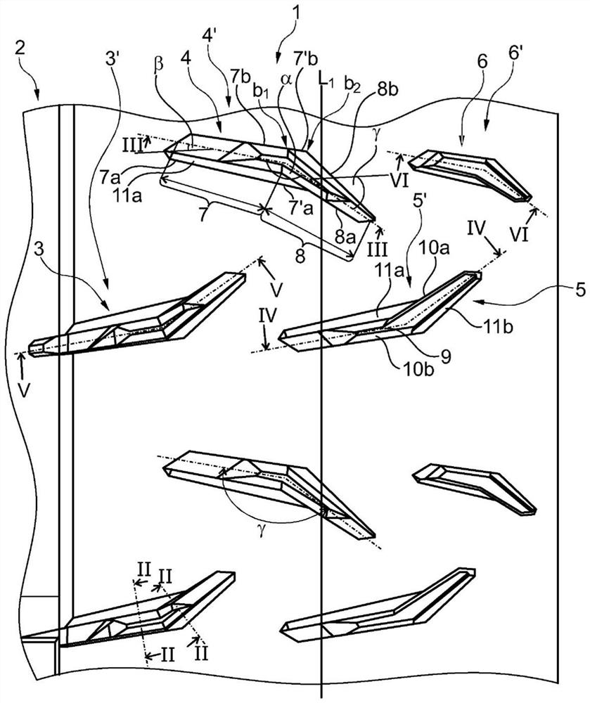
[0024] The pneumatic tire for vehicles embodied according to the invention is in particular a tire of radial construction for passenger cars, vans or light trucks. A "tread band" in the sense of the present invention encircles the tread in the circumferential direction and is equipped with grooves which either run completely within the tread band or at least with one of their ends are within the tread band termination.
[0025] exist figure 1 shows a circumferential section of a tread band 1 on the shoulder side of a tread of a pneumatic tire for a vehicle, which is bounded on the inside of the tread by a circumferential groove 2 . A vehicle pneumatic tire whose tread has the tread band 1 only in one of its shoulders is preferably mounted on the vehicle such that the tread band 1 runs along the tire assigned to the inside of the vehicle in the installed state of the vehicle pneumatic tire. Tread shoulder positioning. Alternatively, the tread of a vehicle pneumatic tire may ...
PUM
Abstract
A pneumatic vehicle tire of radial construction having a tread with at least one tread band (1) bounded laterally by at least one circumferential groove (2) and circumferentially Circumferential in direction, the tread band is equipped on its circumference with at least one row of lugs (3', 4', 5') having a plurality of lugs (3, 4, 5, 6) extending parallel to each other , 6'), wherein each transverse groove (3, 4, 5, 6) has a groove bottom (9) and two groove walls (10a, 10b) and two connected first and a second groove section (7, 8), which enclose an obtuse angle (α) with respect to the center line of the transverse groove (3, 4, 5, 6) extending in the direction of the groove, wherein the sipe segments (7, 8) are respectively bounded on the outer surface of the tread band by two rectilinearly extending sipe edges (7a, 7b, 8a, 8b), and wherein the first sipe segment (7 ) are connected to the groove edges (8a, 8b) of the second groove section (8). The first sipe section (7) extends at an angle (β) of up to 20° with respect to the axial direction, the second sipe section (8) at an angle of 30° to 50° with respect to the axial direction (γ) extension, wherein in each groove section (7, 8) at each groove wall (10a, 10b) is provided with a bevel forming towards and along the groove wall (10a, 10b) bounding Chamfers (11a, 11b) extending from the groove edges (7a, 8b), wherein the chamfers (11a, 11b) extend along the groove edges (7a, 8b) which are not connected to one another.
Description
technical field [0001] The invention relates to a pneumatic vehicle tire of radial construction having a tread with at least one tread band laterally delimited by at least one circumferential groove and encircling in the circumferential direction , which is provided on its circumference with at least one row of lugs having a plurality of lugs extending parallel to each other, each lug having a base and two walls and in plan view Two first and second groove segments connected to each other, these two groove segments enclose an obtuse angle with respect to the center line of the transverse groove extending in the direction of the groove, wherein these groove segments are in the tread band The outer surface is bounded by two rectilinearly extending sipe edges respectively, and wherein the sipe edge of the first sipe section is connected to the sipe edge of the second sipe section. Background technique [0002] A pneumatic vehicle tire of this type is known, for example, from D...
Claims
Application Information
Patent Timeline
Application Date:The date an application was filed.
Publication Date:The date a patent or application was officially published.
First Publication Date:The earliest publication date of a patent with the same application number.
Issue Date:Publication date of the patent grant document.
PCT Entry Date:The Entry date of PCT National Phase.
Estimated Expiry Date:The statutory expiry date of a patent right according to the Patent Law, and it is the longest term of protection that the patent right can achieve without the termination of the patent right due to other reasons(Term extension factor has been taken into account ).
Invalid Date:Actual expiry date is based on effective date or publication date of legal transaction data of invalid patent.