Variable step pitch head-tail width control method of fixed width machine

A width control and width-fixing machine technology, applied in the direction of metal rolling stands, metal rolling mill stands, etc., can solve the problem of not being able to effectively control the width of the head and tail

Active Publication Date: 2019-05-31
BEIJING SHOUGANG CO LTD
View PDF8 Cites 2 Cited by
  • Summary
  • Abstract
  • Description
  • Claims
  • Application Information

AI Technical Summary

Problems solved by technology

[0005] The embodiment of the present invention provides a head-to-tail width control method with a variable step-pitch for a width-fixing machine, which solves the problem i...

Method used


Image

  • Variable step pitch head-tail width control method of fixed width machine
  • Variable step pitch head-tail width control method of fixed width machine
  • Variable step pitch head-tail width control method of fixed width machine

Examples


Embodiment 1

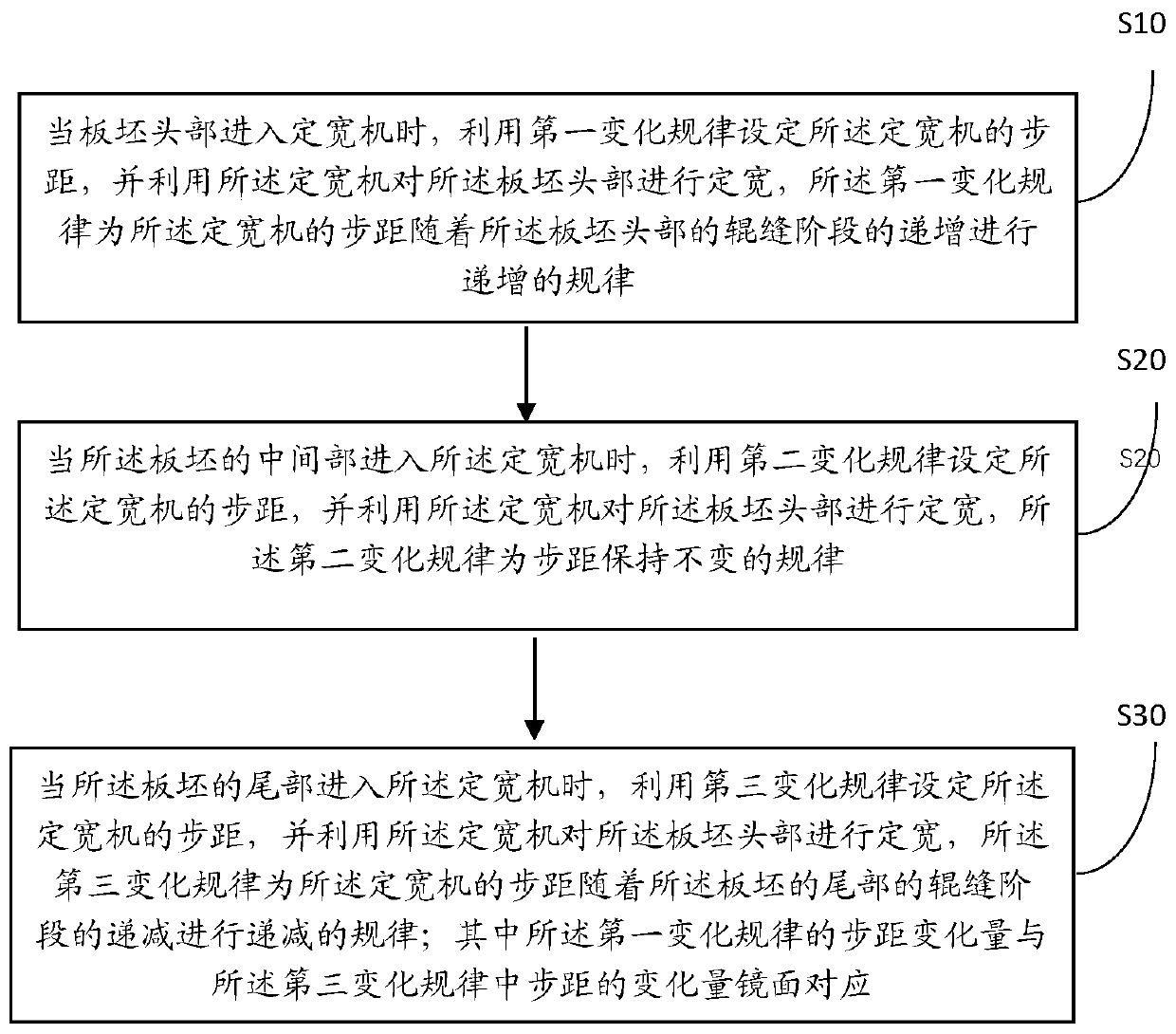
[0032] figure 1 It is a schematic flow chart of a head and tail width control method with variable step pitch for a fixed-width machine in an embodiment of the present invention. The embodiment of the present invention provides a head-to-tail width control method with variable step distance for a fixed-width machine, please refer to Figure 1-4 , the method includes:

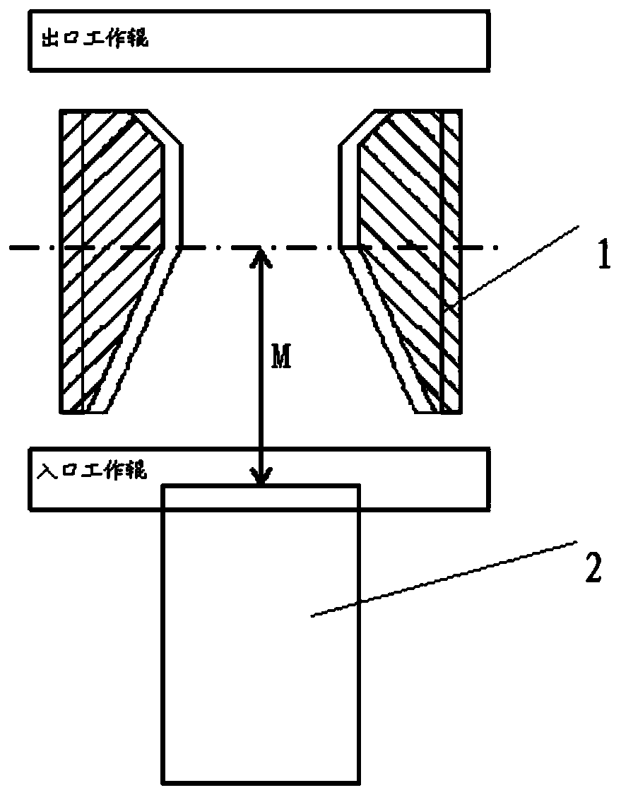
[0033] Step 10: When the head of the slab enters the width-fixing machine 1, use the first change law to set the step distance of the width-fixing machine 1, and use the width-fixing machine 1 to measure the head of the slab 2 Width, the first change law is the law that the step distance of the width-sizing machine 1 increases in multiple stages with the increase of the roll gap stage at the head of the slab 2 .

[0034]Further, the slab head is divided into multiple stages according to the roll gap, at least including: the primary roll gap of the head, the secondary roll gap of the head, and the tertiary roll...

Embodiment 2

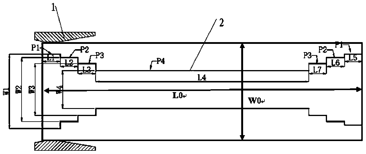
[0053] In order to better introduce the technical characteristics and application of a head-to-tail width control method for a fixed-width machine variable step pitch of the present invention, the application of the present invention will be described in detail below in conjunction with specific embodiments. Please refer to Figure 5-7.

[0054] The embodiment of the present invention is a specific application of a hot rolling mill using a head-to-tail width control method of the present invention with a variable step pitch for a fixed-width machine. The pipeline steel X80 with a higher hardness level and a larger amount of width reduction is selected for testing. The test volume 20 pieces. Raw material specification: 230*1650*10000, finished product specification: 22*1450mm, the theoretical width reduction amount of fixed width machine 1 is 200mm, the actual width reduction amount is 245mm, the step distance of fixed width machine 1 is set to P1=100mm, P2=P3=200mm, P4=300mm,...


PUM

PropertyMeasurementUnit
Widthaaaaaaaaaa
Lengthaaaaaaaaaa

Abstract

The invention provides a variable step pitch head-tail width control method of a fixed width machine. The method comprises the steps that the step pitch of the fixed width machine is set according toa first variation rule when the head of a plate blank enters the fixed width machine, and the first variation rule means that the step pitch of the fixed width machine is increased with the roll gap of the head of the plate blank in a staged mode; when the middle portion of the plate blank enters the fixed width machine, the width of the head of the plate blank is fixed through the fixed width machine, and the step pitch is constant according to a second variation rule; when the tail of the plate blank enters the fixed width machine, the step pitch of the fixed width machine is set in accordance with a third variation rule, and the third variation rule means that the step pitch is decreased in a multi-staged mode; and the variation amounts of all the stage of the first variation rule and the third variation rule are in mirror symmetry. The method achieves the technical effects that through layered control over the step pitch of the fixed width machine, the problem that the head end andthe tail end of metal of steel with high hardness level and widened amount are not restrained, and consequently width reduction is caused is effectively solved, the width control precision of the fixed width machine is effectively improved, and the product yield is increased.

Description

technical field [0001] The invention relates to the technical field of rough rolling of hot-rolled strip steel, in particular to a head-to-tail width control method with variable step pitch of a fixed-width machine. Background technique [0002] The width control of hot rolling mainly depends on the fixed width machine and the vertical roll. Wide range 0-50mm. According to the research on the accuracy of hot rolling width control equipment, it is found that after the slab is hit by the width fixing machine, the head and tail of the intermediate slab will lose width, and with the increase of the width reduction, the head and tail loss of width will become more obvious; When the head and tail width loss is serious, the vertical roller cannot be eliminated by short-stroke adjustment, resulting in excessive head and tail width of the finished product, which cannot meet customer needs and affects the yield of finished products. [0003] However, the applicant of the present inv...

Claims


Application Information

Patent Timeline
IPC IPC(8): B21B37/22
Inventor 霍光帆崔二宝刘丰吕坤张月林辛艳辉刘志王占东周阳王伦
Owner BEIJING SHOUGANG CO LTD
Why Eureka
Try Eureka