Rotor for rotating electrical machine, and method of manufacturing rotor for rotating electrical machine

A technology for rotating electrical machines and rotors, applied in the field of rotors for rotating electrical machines, can solve problems such as difficulty and reduce cogging torque and torque fluctuations

CN109964388AActive Publication Date: 2019-07-02AISIN AW CO LTD +1
15 Cites 0 Cited by

Patent Information

Authority / Receiving Office
CN · China
Patent Type
Applications(China)
Current Assignee / Owner
Publication Date
2019-07-02

Smart Images

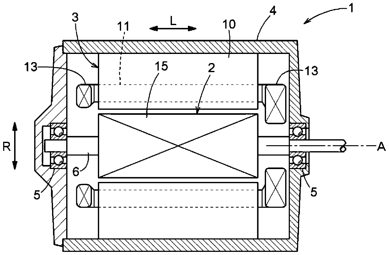
  • Figure 1
    Figure 1
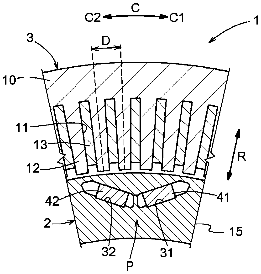
  • Figure 2
    Figure 2
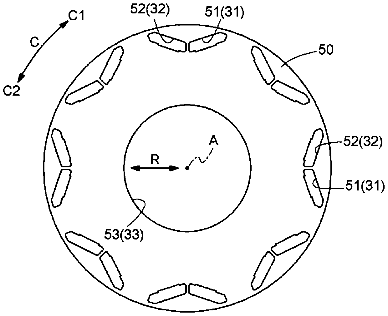
  • Figure 3
    Figure 3
Patent Text Reader

Abstract

A rotor core 15 is provided with a stacked structure 20 in which a plurality of magnetic plates 50 are stacked in an axial direction L. In the stacked structure 20, the plurality of magnetic plates 50are arranged in such a way that the positions thereof are offset from one another to one side in a circumferential direction C by a fixed angle with increasing distance towards one side in the axialdirection L. Magnet insertion holes 31, 32 are formed by means of a plurality of through-holes which penetrate in the axial direction L through all the plurality of magnetic plates 50. Permanent magnets 41, 42 have a shape that is twisted about an axis A such that the permanent magnets 41, 42 are accommodated into the magnet insertion holes 31, 32 from the outside in the axial direction L.
Need to check novelty before this filing date? Find Prior Art

Description

technical field

[0001] The present invention relates to a rotor for a rotating electric machine including a rotor core and permanent magnets embedded in the rotor core, and a method for manufacturing the same. Background technique

[0002] As an example of a rotor for a rotating electric machine, JP 2015-115985 A (Patent Document 1) discloses a rotor having a stepped skew structure. Specifically, the rotor core 1 of the rotor 3 of Patent Document 1 is divided into a plurality of blocks in the axial direction. Furthermore, the blocks are shifted in the circumferential direction to form a stepped skew. Adopting such a stepped skew structure can reduce cogging torque and torque ripple.

[0003] However, in the structure described in Patent Document 1, the plurality of permanent magnets arranged in the axial direction are shifted in the circumferential direction in stages for each of the plurality of blocks, so that the effect of suppressing sudden changes in the magnetic flux...

Examples

Embodiment Construction

[0027] Embodiments of the rotor for a rotating electric machine and its manufacturing method will be described with reference to the drawings. In addition, in the following description, "axial direction L", "radial direction R", and "circumferential direction C" refer to the axis A (refer to figure 1 etc.) as the benchmark definition. The axis A is an imaginary axis, and the rotor 2 rotates around the axis A. And, if Figure 4 etc., let one side in the axial direction L be referred to as the "first axial side L1", and the other side in the axial direction L (the side opposite to the first axial side L1) be referred to as the "second axial side". side L2". In addition, one side in the circumferential direction C is referred to as "the first side C1 in the circumferential direction", and the other side in the circumferential direction C (the side opposite to the first side C1 in the circumferential direction) is referred to as "the second side C2 in the circumferential direct...