Gas-liquid separator and compressor

A gas-liquid separator, gas-liquid separation technology, applied in refrigerators, refrigeration and liquefaction, refrigeration components, etc., can solve problems such as impeding impurities, reducing compressor performance, increasing refrigerant flow resistance, etc., to increase flow resistance , improve performance and prevent liquid shock

Pending Publication Date: 2019-08-02
ZHUHAI LANDA COMPRESSOR +1
View PDF0 Cites 1 Cited by
  • Summary
  • Abstract
  • Description
  • Claims
  • Application Information

AI Technical Summary

Problems solved by technology

[0003] A gas-liquid separator is disclosed in the prior art. In order to improve the effect of refrigerant gas-liquid separation, a flow guiding part is provided between the air inlet pipe and the air outlet pipe. The flow guide part can change the flow direction of the fluid entering the air outlet pipe to prevent The liquid refrigerant flows directly to the outlet pipe; in order to prevent impurities in the pipeline (such as iron filings and copper filings) from entering the compressor directly, a filter assembly is installed between the inlet pipe and the exhaust pipe of the gas-liquid separator to prevent Impurities enter the compressor, but the filter screen assembly will increase the flow resistance of the refrigerant while blocking the impurities, thereby reducing the performance of the compressor

Method used


Image

  • Gas-liquid separator and compressor
  • Gas-liquid separator and compressor
  • Gas-liquid separator and compressor

Examples


Embodiment Construction

[0040] The technical solutions of the present invention will be clearly and completely described below in conjunction with the accompanying drawings. Apparently, the described embodiments are some of the embodiments of the present invention, but not all of them. Based on the embodiments of the present invention, all other embodiments obtained by persons of ordinary skill in the art without making creative efforts belong to the protection scope of the present invention.

[0041] In addition, the technical features involved in the different embodiments of the present invention described below may be combined with each other as long as there is no conflict with each other.

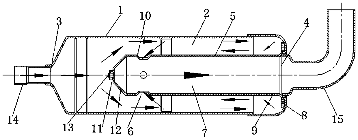
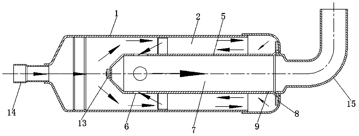
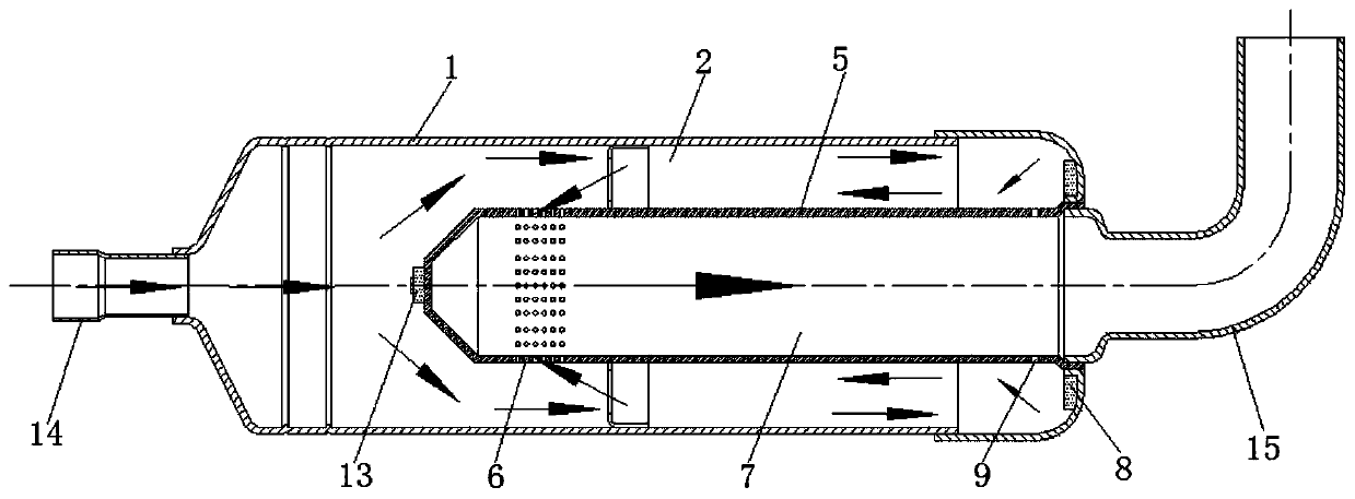
[0042] like Figure 1-Figure 6 As shown, this embodiment provides a gas-liquid separator, including: a housing 1, an inlet 3, an outlet 4, a draft tube 5 and an impurity adsorption device.

[0043] The shell 1 is provided with a gas-liquid separation chamber 2; the inlet 3 is set at one end of the shell 1 an...


PUM


Abstract

The invention provides a gas-liquid separator. The gas-liquid separator comprises a shell, an inlet, an outlet, a flow guide pipe and an impurity absorption device, wherein the shell is provided witha gas-liquid separation cavity; the inlet is formed in one end of the shell, and communicates with the gas-liquid separation cavity; the outlet is formed in the other end of the shell and communicateswith the gas-liquid separation cavity; the flow guide pipe is arranged in the gas-liquid separation cavity and extends from the outlet towards the inlet and communicates with the outlet, and the flowguide pipe and the inlet are arranged at intervals; at least one ventilation structure is arranged on the circumferential wall of the flow guide pipe or the end wall of the back inlet, and the ventilation structures are connected with the gas-liquid separation cavity and the inner cavity of the flow guide pipe; and the impurity adsorption device comprises at least one first impurity adsorption structure and is arranged in the gas-liquid separation cavity. Due to the arrangement of the flow guide pipe, liquid refrigerant and impurities are prevented from being directly discharged to the outlet, and the gas-liquid separation effect is improved; and meanwhile, the impurity adsorption device is arranged, so that the effect of inhibiting the impurities is achieved, the impurities are preventedfrom entering the compressor, a pump body assembly is clamped, the flowing resistance of the refrigerant is not increased due to the arrangement of a filter screen, and the performance of the compressor is improved.

Description

technical field [0001] The invention relates to the technical field of air conditioning, in particular to a gas-liquid separator and a compressor. Background technique [0002] The gas-liquid separator is an important part of the air-conditioning system. It has the functions of storage, gas-liquid separation, filtration, noise reduction and refrigerant buffering. The air pipe part is a protective part to prevent liquid refrigerant from flowing into the compressor and causing liquid shock. During the operation of the air conditioning system, the refrigerant coming out of the evaporator cannot be guaranteed to be completely vaporized, and there will be liquid refrigerant entering the gas-liquid separator. Since the liquid refrigerant itself is heavier than the gas, it will directly fall into the gas-liquid separator. At the bottom of the cylinder, the vaporized refrigerant enters the compressor from the outlet of the gas-liquid separator, thereby preventing the compressor fro...

Claims


Application Information

Patent Timeline
Patent Type & Authority Applications(China)
IPC IPC(8): F25B43/00
CPCF25B43/00
Inventor 聂军霍喜军李永贵
Owner ZHUHAI LANDA COMPRESSOR
Why Eureka
Try Eureka