U-shaped thin-wall steel-prestress reinforced concrete combined bent cap and thin-wall steel tube concrete pier node structure and construction process

A technology of reinforced concrete and thin-walled steel pipes, applied in the direction of erecting/assembling bridges, bridges, bridge materials, etc., can solve the problems of large component cross-section, insufficient seismic performance, and many reinforcements, so as to achieve strong integrity and ensure stability And construction accuracy, force transmission reliable effect

Pending Publication Date: 2019-11-01
CHONGQING UNIV
View PDF0 Cites 7 Cited by
  • Summary
  • Abstract
  • Description
  • Claims
  • Application Information

AI Technical Summary

Problems solved by technology

In the existing T-shaped single-column pier beams, pier beams and structural beams that mainly bear shear force, there are generally disadvantages such as large cross-sections, many reinforcements, poor ductility, and insufficient seismic performance.

Method used


Image

  • U-shaped thin-wall steel-prestress reinforced concrete combined bent cap and thin-wall steel tube concrete pier node structure and construction process
  • U-shaped thin-wall steel-prestress reinforced concrete combined bent cap and thin-wall steel tube concrete pier node structure and construction process
  • U-shaped thin-wall steel-prestress reinforced concrete combined bent cap and thin-wall steel tube concrete pier node structure and construction process

Examples


Embodiment 1

[0048] This embodiment discloses a U-shaped thin-walled steel-prestressed reinforced concrete composite cover beam and a thin-walled concrete-filled steel pipe pier joint structure, including a U-shaped thin-walled steel-prestressed reinforced concrete composite cover beam and a thin-walled steel pipe concrete pier 7 .

[0049] see Figure 9 Or 10, the upper end of the thin-walled steel pipe concrete pier column 7 is connected to the lower surface of the U-shaped thin-walled steel-prestressed reinforced concrete composite cover beam mid-span, and the U-shaped thin-walled steel plate is welded inside to strengthen the connection and strengthen the stressed Stiffeners.

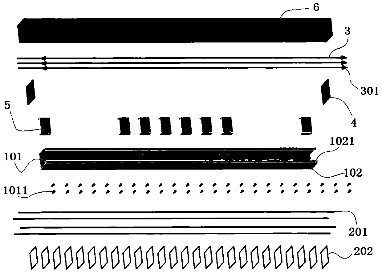
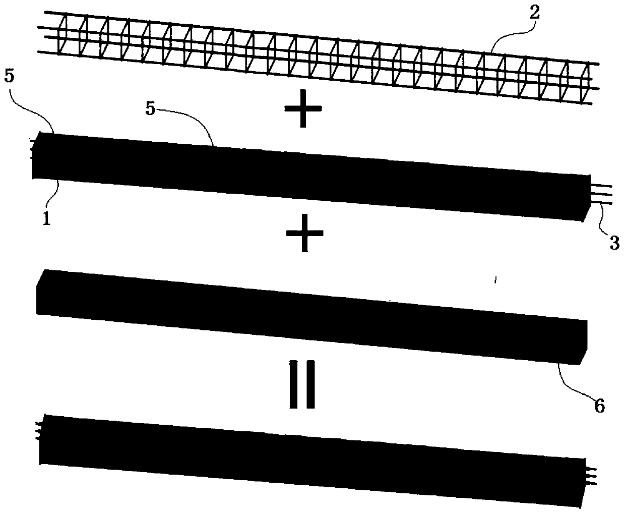
[0050] The U-shaped thin-walled steel-prestressed reinforced concrete composite cover beam includes a U-shaped thin-walled steel plate 1, a steel skeleton 2 and several prestressed tendons 3.

[0051] The U-shaped thin-walled steel plate 1 is processed by welding the thin-walled steel plate, and the processing ...

Embodiment 2

[0067] This embodiment discloses a U-shaped thin-walled steel-prestressed reinforced concrete composite cover beam and a thin-walled concrete-filled steel pipe pier joint structure, including a U-shaped thin-walled steel-prestressed reinforced concrete composite cover beam and a thin-walled steel pipe concrete pier 7 .

[0068] see Figure 9 Or 10, the upper end of the thin-walled concrete filled steel pipe pier 7 is connected to the lower surface of the mid-span of the U-shaped thin-walled steel-prestressed reinforced concrete composite cover beam.

[0069] The U-shaped thin-walled steel-prestressed reinforced concrete composite cover beam includes a U-shaped thin-walled steel plate 1, a steel skeleton 2 and several prestressed tendons 3.

[0070] see figure 1 , the cross-section of the U-shaped thin-walled steel plate 1 is U-shaped, with an opening at the upper end and a closed bottom at the lower end.

[0071] Below the opening is the inner cavity of the U-shaped thin-wal...

Embodiment 3

[0078] The main structure of this embodiment is the same as that of Embodiment 2, further, refer to figure 1 , 6 , 7 or 8, a number of pegs 1011 are welded on the inner surface of the bottom plate I101.


PUM


Abstract

The invention discloses a U-shaped thin-wall steel-prestress reinforced concrete combined bent cap and thin-wall steel tube concrete pier node structure and a construction process. The structure comprises a U-shaped thin-wall steel-prestress reinforced concrete combined bent cap and a thin-wall steel tube concrete pier, when the thin-wall steel tube concrete pier and the U-shaped thin-wall steel-prestress reinforced concrete combined bent cap are connected, a connecting piece, an ear plate, a telescopic threaded steel tube, a platform beam, a telescopic steel rope and a hoop are arranged on the thin-wall steel tube concrete pier, the stability of the installation process is ensured, concrete is poured into a machined U-shaped thin-wall steel beam to form the the U-shaped thin-wall steel-prestress reinforced concrete combined bent cap, and when the concrete is solidified to the designed strength, the combined bent cap is formed by tensioning prestressed steel bars embedded in the concrete. According to the structure, the connection between the U-shaped thin-wall steel-prestress concrete combined bent cap and the steel tube concrete pier is reliable, installing is convenient, construction is simple, the seismic resistance and fire resistance are good, and the manufacturing cost is low.

Description

technical field [0001] The invention relates to the field of construction, in particular to the joint structure and construction technology of a U-shaped thin-walled steel-prestressed reinforced concrete composite cover beam and a thin-walled steel pipe concrete pier. Background technique [0002] The cap beam is the beam set on the top of the bridge bent pile pier, also known as the cap beam. Its main function is to support the upper structure of the bridge and transfer all the load to the lower structure. In the current bridge engineering construction, due to the limitation of bridge height, geological and terrain conditions, the lower part of some bridges adopts the structural form of single-column piers and prestressed cap beams. Generally, by setting support points on the pier columns, I-beam or Bailey racks act as cap beam support brackets. Among the existing T-shaped single-column pier beams, pier beams and structural beams mainly bearing shear force, there are commo...

Claims


Application Information

Patent Timeline
Patent Type & Authority Applications(China)
IPC IPC(8): E01D19/02E01D21/00
CPCE01D19/02E01D21/00E01D2101/285
Inventor 刘界鹏陈古平伊廷华王宣鼎周绪红
Owner CHONGQING UNIV
Why Eureka
Try Eureka