Energy-gathering pumping device with air inflow controlling ball valve, and pumping method

A water pumping device and air intake technology, which is applied to water supply devices, water supply main pipelines, water supply pipeline systems, etc., to achieve the effects of simple structure, convenient operation, and reduced related expenses

Active Publication Date: 2019-11-05
WUHAN UNIV
View PDF9 Cites 2 Cited by
  • Summary
  • Abstract
  • Description
  • Claims
  • Application Information

AI Technical Summary

Problems solved by technology

[0003] In order to overcome the deficiencies in the prior art, this application provides a low-energy energy-gathering water pumping device, a ball valve for controlling the amount of air intake and a pumping method, which can reduce the height difference required for water intake by the device to meet higher demands; When the water reaches a certain amount, it can automatically open or close the sealed water storage tank without manual opening; a Venturi tube is added to the device to use the negative pressure when the water flows through to supplement the negative pressure value of the device to a certain extent, which improves the fault tolerance rate , making the device more effective

Method used


Image

  • Energy-gathering pumping device with air inflow controlling ball valve, and pumping method
  • Energy-gathering pumping device with air inflow controlling ball valve, and pumping method
  • Energy-gathering pumping device with air inflow controlling ball valve, and pumping method

Examples


Embodiment 1

[0028] An energy-gathering pumping device, comprising n-shaped pipeline 1, n-shaped pipeline negative pressure pipeline 8, water pumping pipeline 10 and sealed water storage tank 7, said n-shaped pipeline 1 is filled with water by vacuum pump respectively, and the shorter end is placed on the overflow Under the water surface of the higher side of the weir water level, the longer end is placed under the water surface of the lower side of the overflow weir water level, and the lowest end of the longer end is lower than the lowest end of the shorter end, and the top of the n-shaped pipe 1 is fixed by The n-shaped pipeline negative pressure pipeline 8 connected with the n-shaped pipeline negative pressure pipeline valve 9 communicates with the sealed water storage tank 7, the water inlet of the n-shaped pipeline 1 is provided with an n-shaped pipeline water inlet valve 2, and the water outlet is provided with n Shaped pipeline water outlet valve 18 is characterized in that: also co...

Embodiment 2

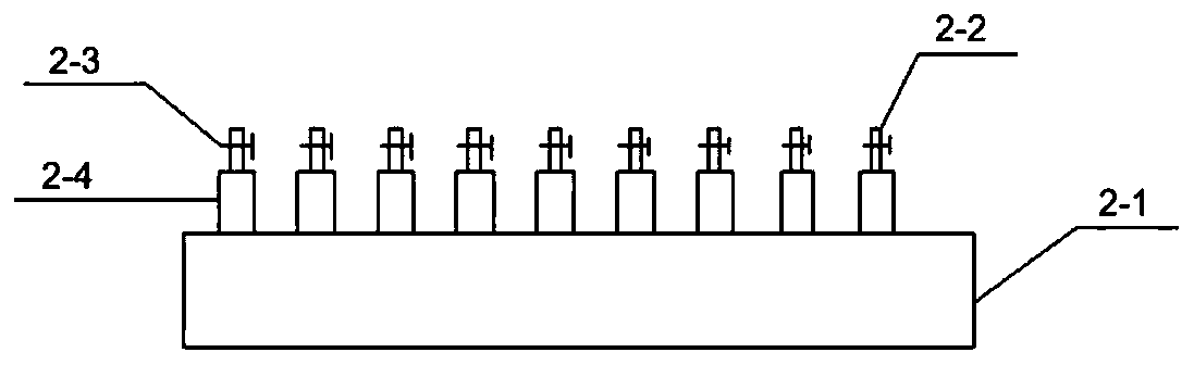
[0034]A ball valve for controlling intake air volume, comprising:

[0035] - the main pipe 2-1, the two ends of the main pipe 2-1 have an inlet and an outlet, and a number of installation holes are opened on the side wall;

[0036] - the air intake pipe 2-2, the air intake pipe 2-2 communicates with the atmosphere;

[0037] ——Valve 2-3 for controlling the opening and closing of the intake pipe;

[0038] - the protective cover 2-4, the protective cover 2-4 is socketed with the air intake pipe.

[0039] For the aforementioned ball valve for controlling the amount of intake air, preferably, several intake pipes 2-2 are arranged on the side wall of the main pipe 2-1.

[0040] In the above-mentioned ball valve for controlling the intake air volume, preferably, the intake air volume of the ball valve and the water-steam mixing ratio at the suction pipe are determined by the number of open intake pipes 2-2.

[0041] For the aforementioned ball valve for controlling the amount of i...

Embodiment 3

[0043] A method of pumping water utilizing the above-mentioned device, comprising the steps of:

[0044] 1. Close the water inlet valve 2 and the water outlet valve 18 of the η-shaped pipeline 1, and start the vacuum pump to inject water into the η-shaped pipeline;

[0045] ② After the n-shaped pipeline 1 is filled with water, close the negative pressure pipeline valves 6 and 9, open the water inlet valve 2 and the water outlet valve 18 of the n-shaped pipeline 1, and the water flow continuously flows downstream;

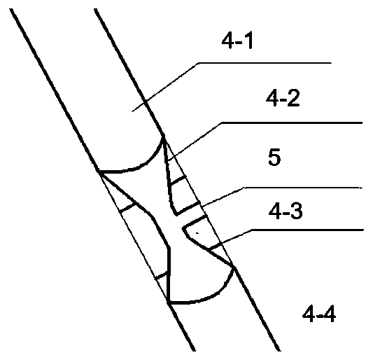
[0046] ③Close the ventilation valve 14 and the water tap 16 of the sealed water storage tank, and the pumping pipeline valve 13, open the negative pressure pipeline valves 6 and 9 of the sealed water storage tank, the gas in the sealed water storage tank 7 is gradually absorbed by the negative pressure on the top of the n-shaped pipeline 1 The negative pressure pipeline 5 at the narrow part of the pipeline 8 and the Venturi tube 4 is drawn out, and the water storage...


PUM


Abstract

The invention provides an energy-gathering pumping device with an air inflow controlling ball valve, and a pumping method. The device comprises an eta-shaped pipeline, a Venturi pipe, negative pressure pipelines, a pumping pipeline and a sealed water storage tank, wherein a water inlet of the eta-shaped pipeline is located upstream, and a water outlet is located downstream; a water inlet end of the Venturi pipe is located below a downflow weir, and an water outlet is located on the downstream liquid surface; the top of the eta-shaped pipeline and the narrowest part of the Venturi pipe communicate with the sealed water storage tank through the negative pressure pipelines provided with negative pressure valves; the side of the sealed water storage tank communicates with an upstream water source through the pumping pipeline provided with a sealed water storage tank valve, the air inflow controlling ball valve and a pumping pipeline valve; a ventilation valve is arranged at the upper partof the sealed water storage tank, and the bottom of the sealed water storage tank is connected to a buoyancy valve and a water faucet. The energy-gathering pumping device has the advantages that energy of the flow drop between the upstream and downstream of the mountain stream can be used to pump water, unattended pumping can be achieved after a siphon is started, and thus, operation is safe, related expenses on administrative staff in a pump station are greatly reduced, and unattended management for a pump station is truly achieved.

Description

technical field [0001] The invention relates to the technical field of water conservancy drainage and irrigation, in particular to an energy-gathering water pumping device and a water pumping method with a ball valve for controlling the amount of air intake. Background technique [0002] Considering economic factors, my country seldom sets up pumping stations in places where the water head difference is less than 6m, which makes it difficult to use water conveniently in rural areas in remote areas; , need to consume a lot of fuel or electric energy. Therefore, how to improve the pumping efficiency, reduce the energy consumption of irrigation and drainage or not rely on electricity consumption, and how to improve the overall economics of the device has been perplexing the majority of scientific researchers. The Chinese invention patent with the application number CN201510647572.3 provides "a kind of energy-gathering water pumping device and water pumping method", including mu...

Claims


Application Information

Patent Timeline
Patent Type & Authority Applications(China)
IPC IPC(8): E03B5/00E03B7/07
CPCE03B5/00E03B7/07
Inventor 苏凯周力平张文宇任晶莹王文宇澄刘宗奇陶奕
Owner WUHAN UNIV
Why Eureka
Try Eureka