Cutting device for electromechanical processing

A cutting device, electromechanical technology, applied in metal processing and other directions, can solve problems such as unsatisfactory cutting effect and inability to cut materials at different angles, and achieve the effect of avoiding dust flying, facilitating centralized processing, and ensuring effectiveness

Active Publication Date: 2019-12-10
江苏新界机械配件有限公司
View PDF10 Cites 1 Cited by
  • Summary
  • Abstract
  • Description
  • Claims
  • Application Information

AI Technical Summary

Problems solved by technology

[0003] The existing electromechanical processing and cutting devices cannot cut materials at different angles during use, resulting in unsatisfactory cutting effects. Therefore, in view of the above status quo, it is urgent to develop an electromechanical processing and cutting device to overcome the shortcomings in current practical applications

Method used


Image

  • Cutting device for electromechanical processing
  • Cutting device for electromechanical processing
  • Cutting device for electromechanical processing

Examples


Embodiment 1

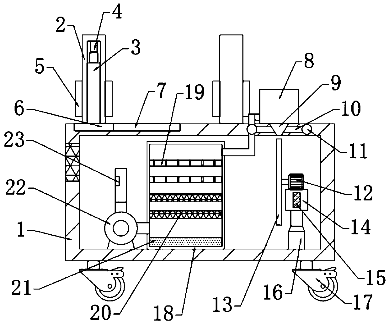
[0026] see Figure 1-3 , in an embodiment of the present invention, an electromechanical processing and cutting device includes a workbench 1, support columns 2 on the left and right sides of the top of the workbench 1, the support columns 2 on the right side are fixedly connected to the workbench 1, and the left side The support column 2 is slidably connected with the workbench 1, a splint 5 is arranged between the support columns 2 on both sides, an opening 9 is arranged on the right side of the top of the workbench 1, and a cutting mechanism is arranged on the lower side of the opening 9. A dust removal mechanism is provided on the left side of the mechanism, and several casters 17 are fixedly connected to the bottom of the workbench 1 .

Embodiment 2

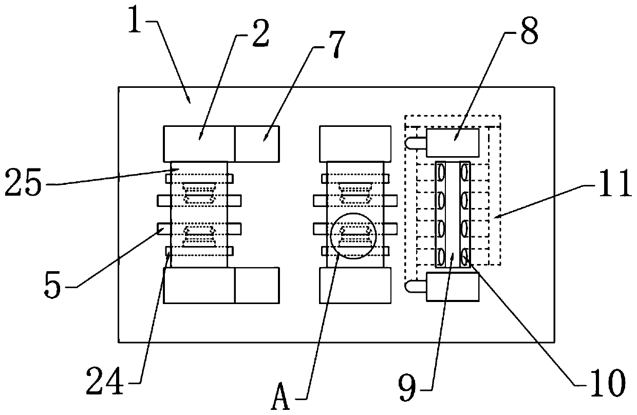
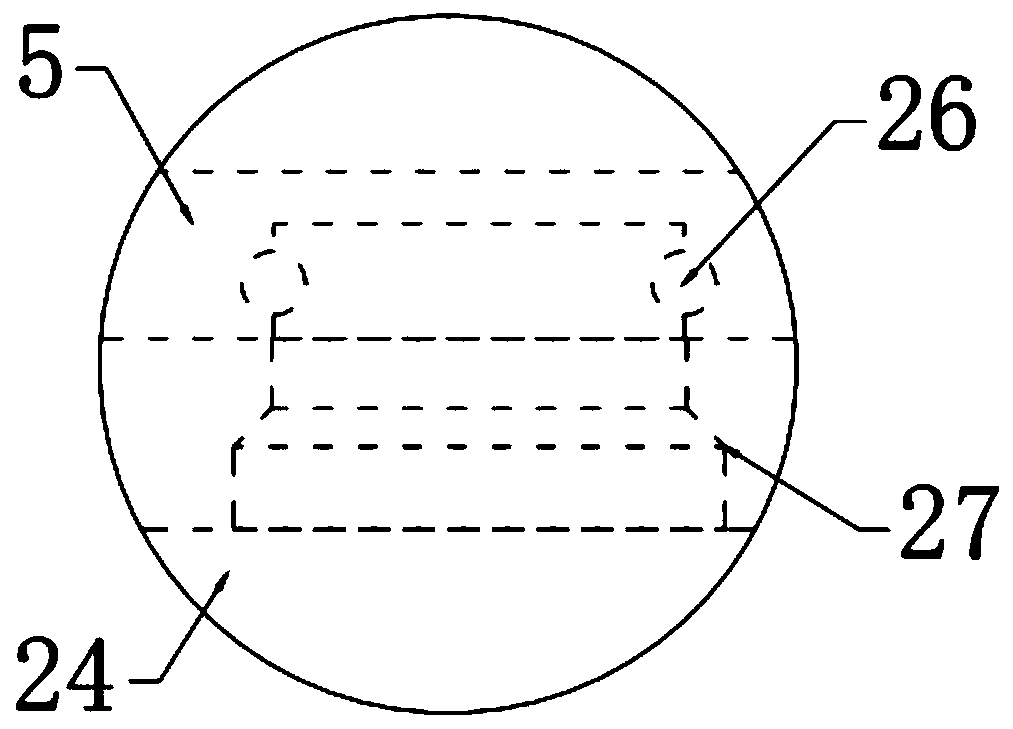
[0028] In this embodiment, a fixed rod 3 is provided on the inner side of the support column 2 on the left side, and the bottom of the fixed rod 3 is fixedly connected with a slider 6 that is slidably connected to the workbench 1. 1. The slide rail 7 at the top is slidably connected, and the support column 2 on the left side is slidably connected with the fixed rod 3. The fixed connection between the fixed rod 3 and the support column 2 is provided with a first telescopic rod 4. The support column on one side 2 is fixedly connected with a fixed plate 25, and the bottom of the fixed plate 25 is fixedly connected with two connecting plates 24, and the opposite side of the connecting plate 24 is provided with a clamping plate 5, and the connection between the clamping plate 5 and the connecting plate 24 A third telescopic rod 27 is arranged between them, the third telescopic rod 27 is fixedly connected with the connecting plate 24, and the third telescopic rod 27 is rotatably conn...


PUM


Abstract

The invention relates to the technical field of electromechanical processing, and in particular to a cutting device for electromechanical processing. The cutting device for the electromechanical processing comprises a workbench, the left and right sides of the top end of the workbench are provided with supporting columns, the supporting column at the right side is fixedly connected with the workbench, the supporting column at the left side is slidingly connected with the workbench, a fixing plate is arranged between the supporting columns at one side, two connecting balls are arranged at the bottom of the fixing plate, the relative sides of the connecting plates are provided with clamping plates, third telescopic rods are arranged between the clamping plates and the connecting plates, thethird telescopic rods are rotationally connected with the clamping plates, an opening is arranged on the right side of the top end of the workbench, a cutting mechanism is arranged on the lower side of the opening, and a dust removing mechanism is arranged on the left side of the cutting mechanism, through using the stretching of a first telescopic rod, the cutting device can drive the supportingcolumn at the left side rod to lift, so the plate fixed by the clamping plates rotates, and the cutting blade can cut the plate at different angles.

Description

technical field [0001] The invention relates to the technical field of electromechanical processing, in particular to a cutting device for electromechanical processing. Background technique [0002] Cutting is a physical action. Cutting in the narrow sense refers to cutting objects with sharp tools such as knives, such as food, wood and other objects with low hardness. Cutting in the broad sense refers to using tools such as machine tools, flames, etc. The cutting device is an indispensable tool used in the industrial field, and has a wide range of applications, while the electromechanical engineering cutting device is used in the manufacturing and production of electromechanical engineering products to adjust the length, width and Thickness cutting device. [0003] The existing electromechanical processing and cutting devices cannot cut materials at different angles during use, resulting in unsatisfactory cutting effects. Therefore, in view of the above status quo, it is ...

Claims


Application Information

Patent Timeline
Patent Type & Authority Applications(China)
IPC IPC(8): B26D1/12B26D7/02B26D7/18B26D5/00
CPCB26D1/125B26D5/00B26D7/015B26D7/02B26D7/1863
Inventor 徐政
Owner 江苏新界机械配件有限公司
Why Eureka
Try Eureka