Coaxial cable fixture driving mechanism

A technology of coaxial cable and drive mechanism, which is applied to circuits, electrical components, circuit/collector parts, etc., can solve problems such as inability to circumscribe, and achieve the effect of easy processing and high rigidity

Active Publication Date: 2019-12-24
深圳市鑫骄阳通讯科技有限公司
View PDF28 Cites 1 Cited by
  • Summary
  • Abstract
  • Description
  • Claims
  • Application Information

AI Technical Summary

Problems solved by technology

This patent can only place single-strand cables, and is only suitable for cables of one thickness, for axial cutting, and cannot be used for ring cutting

Method used


Image

  • Coaxial cable fixture driving mechanism
  • Coaxial cable fixture driving mechanism
  • Coaxial cable fixture driving mechanism

Examples


Embodiment Construction

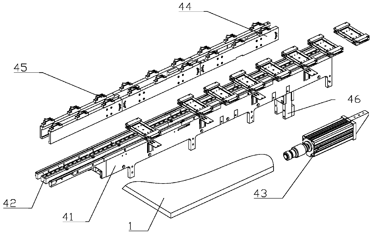
[0019] Such as figure 1 As shown, a driving mechanism of a coaxial cable jig includes a fixed base 41, an intermediate slide bar 42, a material transfer cylinder 43, a sliding plate 44, a pushing assembly 45, a connecting block 46 and a cable jig; the fixed bottom plate 41 is fixed Set on the frame, the fixed base 41 is groove-shaped, the middle sliding bar 42 is installed in the middle of the fixed base 41, and the middle sliding bar 42 is convex; the material-moving cylinder 43 is horizontally arranged on the frame, and the material-moving cylinder The telescopic end of 43 is connected with the sliding plate 44 through the connecting block 46; the sliding plate 44 is moved and matched with the fixed base 41 through the slide rail, and the sliding plate 44 is provided with two parallels; the pushing material The components 45 are arranged on the upper end of the sliding plate 44, and the pushing components 45 are evenly arranged, and the corresponding pushing components 45 on...


PUM


Abstract

The invention relates to the field of transmission line production. A cable driving mechanism comprises a frame, a fixed base, an intermediate sliding bar, a material transfer cylinder, sliding plates, pusher components, connection blocks and a cable fixture. The fixed base is groove-shaped. The intermediate sliding bar is arranged in the middle of the fixed base. The material transfer cylinder ishorizontally arranged on the frame. The telescopic end of the material transfer cylinder is connected with the sliding plates through connection blocks. The sliding plates movably match the fixed base through a sliding rail. Two sliding plates are arranged side by side. The pusher components are arranged on the upper ends of the sliding plates. The pusher components are evenly arranged. The pusher components are used for unidirectionally pushing the fixture to move. The cable fixture comprises a base, a pressure plate, a lock buckle and a rubber pad. The pressure plate is hinged in a turntable. A clamp slot is arranged on the end of the pressure plate. The lock buckle is hinged with the base. A hook is arranged at the vertical part of the lock buckle. The hook matches the clamp slot. According to the invention, cables of two specifications can be arranged, and the mechanism has the advantages of efficient and accurate driving and high rigidity.

Description

technical field [0001] The invention relates to the field of transmission line production, in particular to a driving mechanism for a coaxial cable jig. Background technique [0002] Coaxial cable refers to a cable with two concentric conductors, and the conductor and shield share the same axis. The most common coaxial cable consists of copper conductors separated by insulation, on the outside of the inner insulation is another ring conductor and its insulator, and then the entire cable is surrounded by a PVC jacket. Coaxial cable is used by TV companies between TV subscribers and community antennas, by telephone companies, and is also widely used in corporate intranets and Ethernet. When the coaxial cable is connected and installed, the ends need to be stripped and soldered. Since the cable is difficult to fix, it is often placed in a specific jig for processing. [0003] The State Intellectual Property Office of China has disclosed a high-efficiency full-automatic coaxia...

Claims


Application Information

Patent Timeline
Patent Type & Authority Applications(China)
IPC IPC(8): H01R43/28
CPCH01R43/28
Inventor 陆阳清王凯陈泽楷张鑫洋
Owner 深圳市鑫骄阳通讯科技有限公司
Why Eureka
Try Eureka