Display device and electronic device

A technology for display devices and display screens, which is applied to structural components of electrical equipment, electric heating devices, measuring devices, etc., can solve problems such as display delays and failure to display on the display screen, and achieve improved integration, improved connection strength, and overall structure compact effect

Inactive Publication Date: 2020-01-10
BOE TECH GRP CO LTD
View PDF11 Cites 0 Cited by
  • Summary
  • Abstract
  • Description
  • Claims
  • Application Information

AI Technical Summary

Problems solved by technology

[0004] The main purpose of the present invention is to provide a display device and electronic equipment, so that it can solve the problem of display delay or failure to display in the cold environment of the display screen in the prior art

Method used


Image

  • Display device and electronic device
  • Display device and electronic device
  • Display device and electronic device

Examples


Embodiment 1

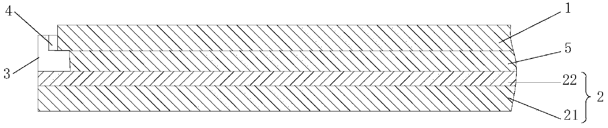
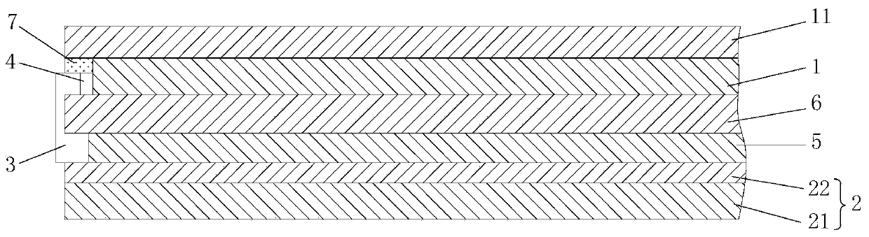
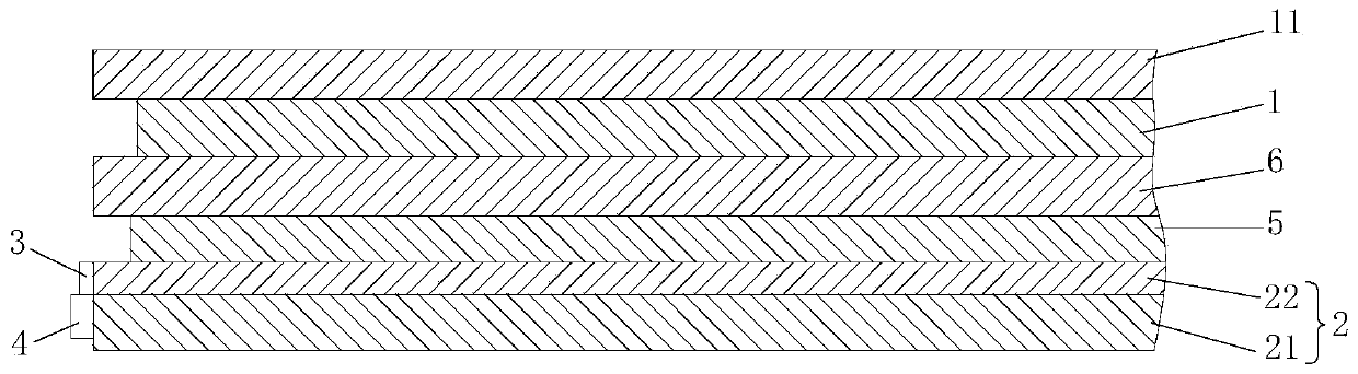
[0048] Such as Figure 1-Figure 3 and Figure 6-Figure 7 As shown, the first embodiment of the present invention proposes a display device, which includes: a stacked display screen 1 and an electrically heated glass layer 2; the electrically heated glass layer 2 includes a stacked first transparent glass layer 21 and Transparent conductive film layer 22, the side of described transparent conductive film layer 22 is connected and is provided with electrical connection terminal 23, for example electrical connection terminal 23 comprises positive electrode 231 and negative electrode 232, and described positive electrode 231 and described negative electrode 232 Connected to the flexible circuit board 3; the thermistor 4, the thermistor 4 is connected to the flexible circuit board 3, and is set close to the display screen 1 for detecting the temperature of the display screen 1; wherein, the The flexible circuit board 3 is arranged along the side of the transparent conductive film ...

Embodiment 2

[0071] An electronic device proposed in Embodiment 2 of the present invention includes: a display device; such as Figure 1-Figure 3 and Figure 6-Figure 7 The display device shown includes: a stacked display screen 1 and an electrically heated glass layer 2; the electrically heated glass layer 2 includes a stacked first transparent glass layer 21 and a transparent conductive film layer 22, and the transparent conductive film The side of layer 22 is connected and provided with positive electrode 231 and negative electrode 232, and described positive electrode 231 and described negative electrode 232 are connected with flexible circuit board 3; Thermistor 4, described thermistor 4 and described flexible circuit board The circuit board 3 is connected and arranged close to the display screen 1 for detecting the temperature of the display screen 1; wherein, the flexible circuit board 3 is arranged along the side of the transparent conductive film layer 22, and part of the flexible...


PUM


Abstract

The invention relates to a display device and an electronic device, and relates to the technical field of display devices. The main adopted technical scheme is as follows: the display device comprisesa display screen and an electric heating glass layer which are arranged in a stacking manner, as well as thermistors, wherein the electric heating glass layer comprises a first transparent glass layer and a transparent conductive film layer which are arranged in a stacking manner, the side edge of the transparent conductive film layer is connected with and provided with an electric connecting end, and the electric connecting end and a flexible circuit board are connected; the thermistors are connected with the flexible circuit board, are arranged attaching to the display screen, and are usedfor detecting the temperature of the display screen; and the flexible circuit board is arranged along the side edge of the transparent conductive film layer, part of the flexible circuit board is positioned in the display device of the stacking structure, and the rest part of the flexible circuit board is positioned outside the display screen and the electric heating glass layer arranged in the stacking manner, and is used for connecting with a processor. With the display device, the display problems occurring in the low-temperature environment can be solved.

Description

technical field [0001] The present invention relates to the technical field of display equipment, in particular to a display device and electronic equipment. Background technique [0002] There are many types of display screens, including liquid crystal display LCD, organic light-emitting diode display OLED, and inorganic light-emitting diode display LED. [0003] With the advancement of technology, display screens are used in various environments, including high-temperature environments, low-temperature environments, and humid environments, and low-temperature environments have certain effects on the normal display of display screens. Further research on low temperature performance. Contents of the invention [0004] The main purpose of the present invention is to provide a display device and electronic equipment, which can solve the problem of display delay or failure to display in the cold environment of the display screen in the prior art. [0005] The purpose of the...

Claims


Application Information

Patent Timeline
Patent Type & Authority Applications(China)
IPC IPC(8): G09F9/35G09F9/33H05B3/86
CPCG09F9/35G09F9/33H05B3/86G02F1/133382H05B3/84H05B2203/013G01K7/22H01L23/345H05B1/023H05B3/03H05B2203/016H05K7/20954
Inventor 马超
Owner BOE TECH GRP CO LTD
Why Eureka
Try Eureka