Rail damping fastener

A vibration-damping fastener and track technology, which is applied in the field of rail transit, can solve problems such as abnormal track gauge expansion, low lateral stiffness, and high cost, so as to reduce construction and later operation and maintenance costs, improve lateral stiffness, and reduce installation costs. height effect

Pending Publication Date: 2020-03-06
CHINA RAILWAY ENG CONSULTING GRP CO LTD
View PDF0 Cites 5 Cited by
  • Summary
  • Abstract
  • Description
  • Claims
  • Application Information

AI Technical Summary

Problems solved by technology

However, it is often impossible to achieve both in actual product design. When the vertical stiffness of the vibration-damping fastener is low, the lateral stiffness is often low, which leads to problems such as abnormal gauge expansion of the track; when the lateral stiffness of the vibration-damping fastener is high Often the vertical stiffness is relatively high, resulting in poor vibration damping effect of fasteners
[0004] In addition, the current market adopts the overall structural design of "two-layer iron backing plate + two-layer elastic body", resulting in a high overall installation height of the vibration-damping fastener. The height from the sleeper to the bottom of the rail is usually above 56mm, while the The installation height of other non-vibration-absorbing fasteners is generally below 45mm
The change of the installation height makes it necessary to reduce the installation height of the sleeper surface to realize the unity with other fasteners when using the vibration damping fastener, which brings unnecessary trouble and high cost to the construction, later operation and maintenance.

Method used


Image

  • Rail damping fastener
  • Rail damping fastener
  • Rail damping fastener

Examples


Embodiment Construction

[0042] In order to make the objectives, technical solutions and advantages of the present invention clearer, the embodiments of the present invention will be described in detail below in conjunction with the accompanying drawings. It should be noted that the embodiments in the application and the features in the embodiments can be combined with each other arbitrarily if there is no conflict.

[0043] In the following description, many specific details are set forth in order to fully understand this article. However, this article can also be implemented in other ways different from those described here. Therefore, the scope of protection of this article is not limited by the specific embodiments disclosed below. .

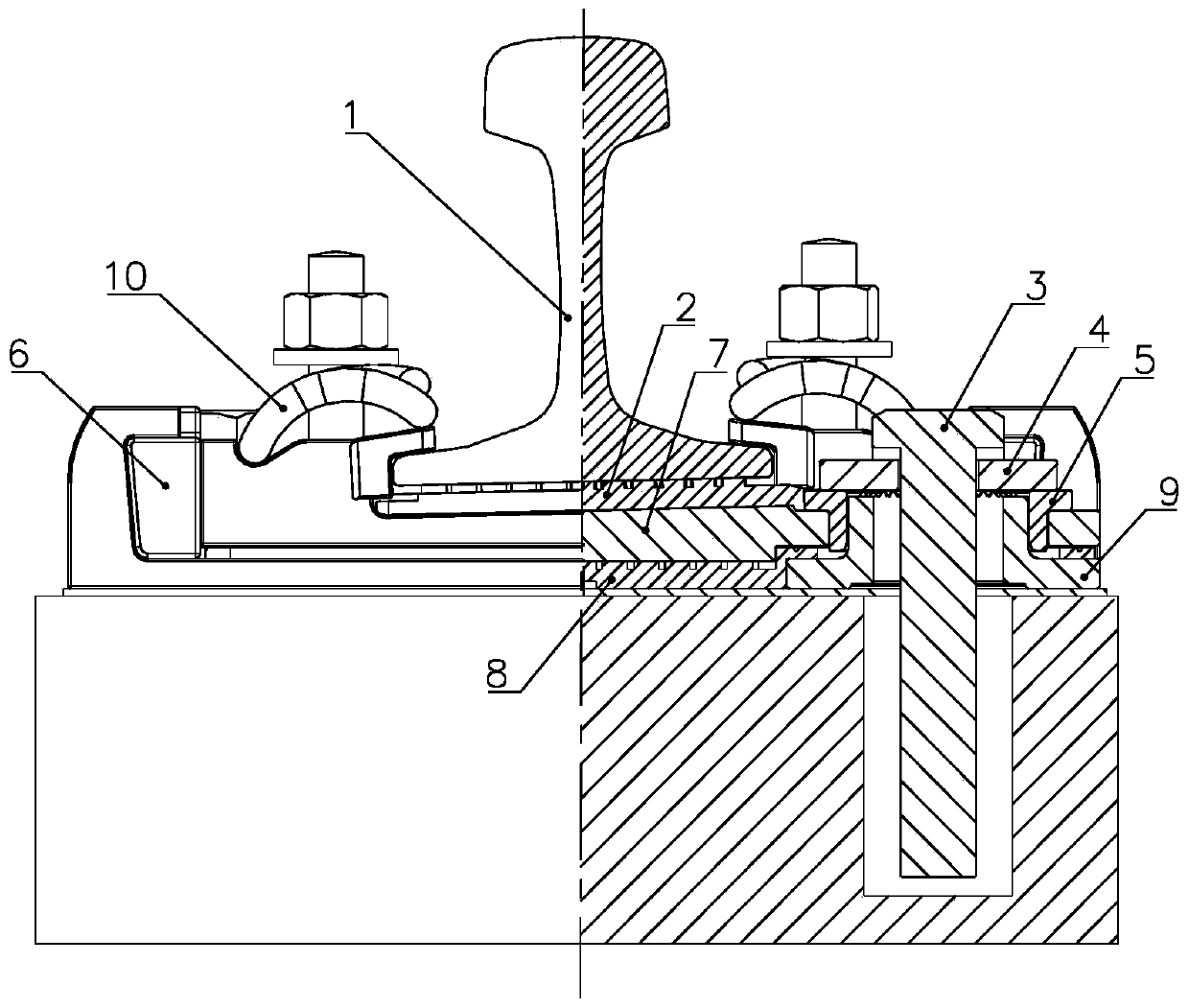
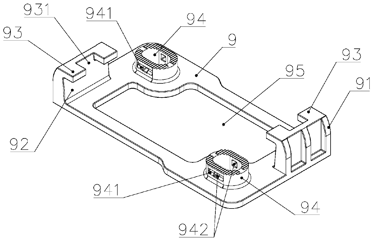
[0044] Such as figure 1 As shown, a rail vibration damping fastener includes an upper backing plate 7, a lower backing plate 9, an under-rail elastic backing plate 2, a middle elastic backing plate 8. Further, the rail vibration damping fastener may also include a lockin...


PUM


Abstract

The invention discloses a rail damping fastener. The rail damping fastener comprises an upper base plate, a lower base plate, an intermediate elastic base plate and an under-rail elastic base plate, the intermediate elastic base plate is arranged between the upper base plate and the lower base plate, the under-rail elastic base plate is arranged on the upper base plate, a boss is arranged on the lower base plate, the upper base plate is externally arranged on the boss in a sleeving mode, a longitudinal first transverse limiting surface is arranged on the upper base plate, a transverse blockingshoulder extending upwards is arranged on the lower base plate, a longitudinal blocking shoulder extending towards the first horizontal limiting surface is arranged at the upper end of the transverseblocking shoulder, the rail damping fastener further comprises a transverse clamping block, and the transverse clamping block is arranged between the first transverse limiting surface and the transverse blocking shoulder. According to the rail damping fastener, by arranging a transverse blocking shoulder structure, the integration of the higher transverse stiffness and the lower vertical stiffness of the rail damping fastener can be achieved without affecting the damping effect of the rail damping fastener.

Description

Technical field [0001] The present invention relates to the technical field of rail transit, in particular to a rail vibration damping fastener. Background technique [0002] In recent years, as the vibration and noise of urban rail transit have become more and more serious, effectively solving this problem has become a key area of ​​research in academia and engineering. At present, various types of damping fasteners have been introduced on the market. Among them, the upper-locking double-layer damping fastener has been widely used due to its high cost performance. However, this type of damping fastener is also used in practical applications. There are certain problems. [0003] The upper locking double-layer vibration damping fastener relies on two layers of elastic backing plates to buffer the vibration and impact of the wheel and rail to achieve a vibration damping effect. At the same time, two layers of iron backing plates are provided in the fastener system. The two layers o...

Claims


Application Information

Patent Timeline
Patent Type & Authority Applications(China)
IPC IPC(8): E01B9/38E01B19/00
CPCE01B9/38E01B19/00
Inventor 孙井林潘涛冉蕾瞿连辉马佳骏黄庆吴凯伟薛玥刘雪锋
Owner CHINA RAILWAY ENG CONSULTING GRP CO LTD
Why Eureka
Try Eureka