Pneumatic and magnetically-controlled retractable deceleration strip

A speed bump and magnetic control technology, applied in the field of intelligent transportation, can solve the problems of reducing the comfort of the vehicle, reducing the service life of the shock absorption system, and strong vibration, so as to reduce the bumpy feeling, increase the comfort, and remind the effect of safe driving

Active Publication Date: 2020-03-24
苏州澎澄企业管理有限公司
View PDF7 Cites 0 Cited by
  • Summary
  • Abstract
  • Description
  • Claims
  • Application Information

AI Technical Summary

Problems solved by technology

[0003] The speed bumps on the road have the effect of reminding passing vehicles to slow down, but most of the current speed bumps are made of hard rubber. When the current speed bumps are used, they often cause a lot of inconvenience. For example, when the vehicle deliberately When passing at a slow speed, because the speed bump cannot be contracted, the vibration will still be felt, and the vibration is relatively strong, which reduces the comfort of the vehicle, and the strong vibration may cause the passengers sitting in the car to shake, which may cause personnel Injury, and the shock absorption system of the vehicle will also be damaged to a certain extent, resulting in a reduction in the service life of the shock absorption system, and the shock absorption system is related to the driving safety of the vehicle. After the shock absorption system is damaged, it is easy to cause traffic accidents, and the consequences are disastrous.

Method used


Image

  • Pneumatic and magnetically-controlled retractable deceleration strip
  • Pneumatic and magnetically-controlled retractable deceleration strip
  • Pneumatic and magnetically-controlled retractable deceleration strip

Examples


Embodiment Construction

[0019] The following will clearly and completely describe the technical solutions in the embodiments of the present invention with reference to the accompanying drawings in the embodiments of the present invention. Obviously, the described embodiments are only some, not all, embodiments of the present invention. Based on the embodiments of the present invention, all other embodiments obtained by persons of ordinary skill in the art without making creative efforts belong to the protection scope of the present invention.

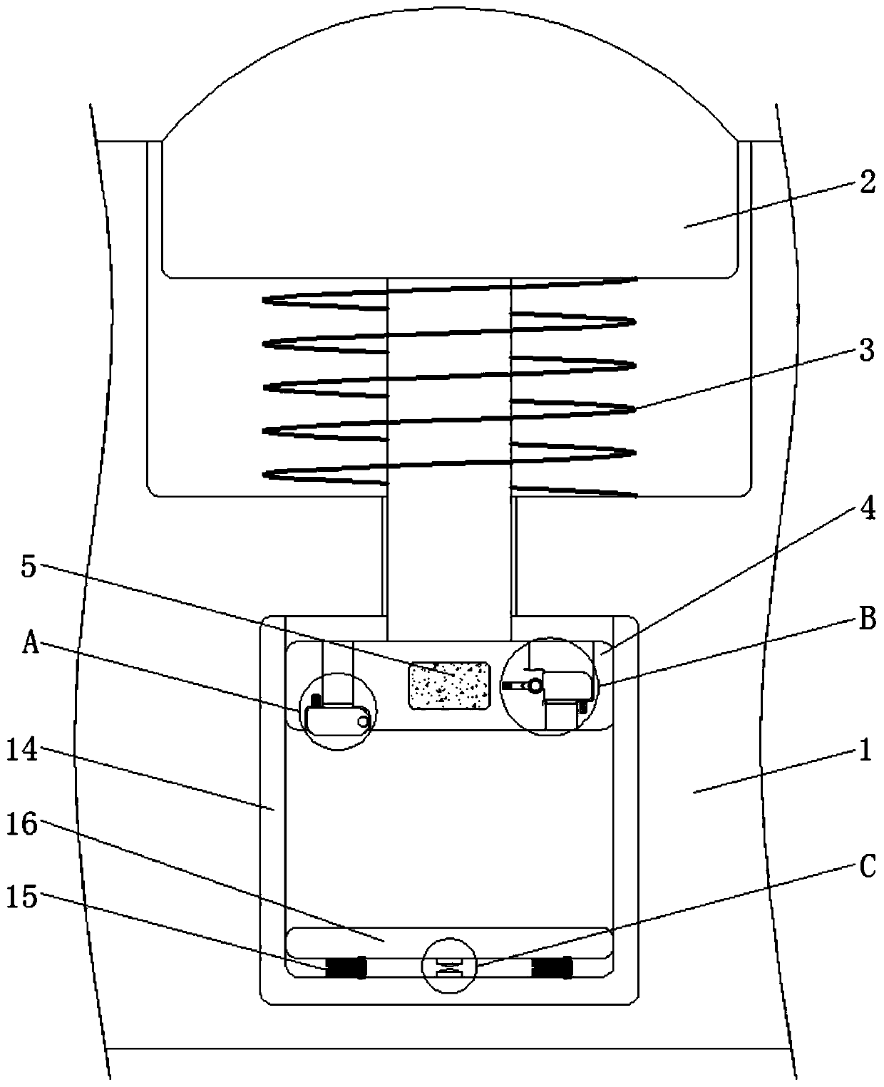
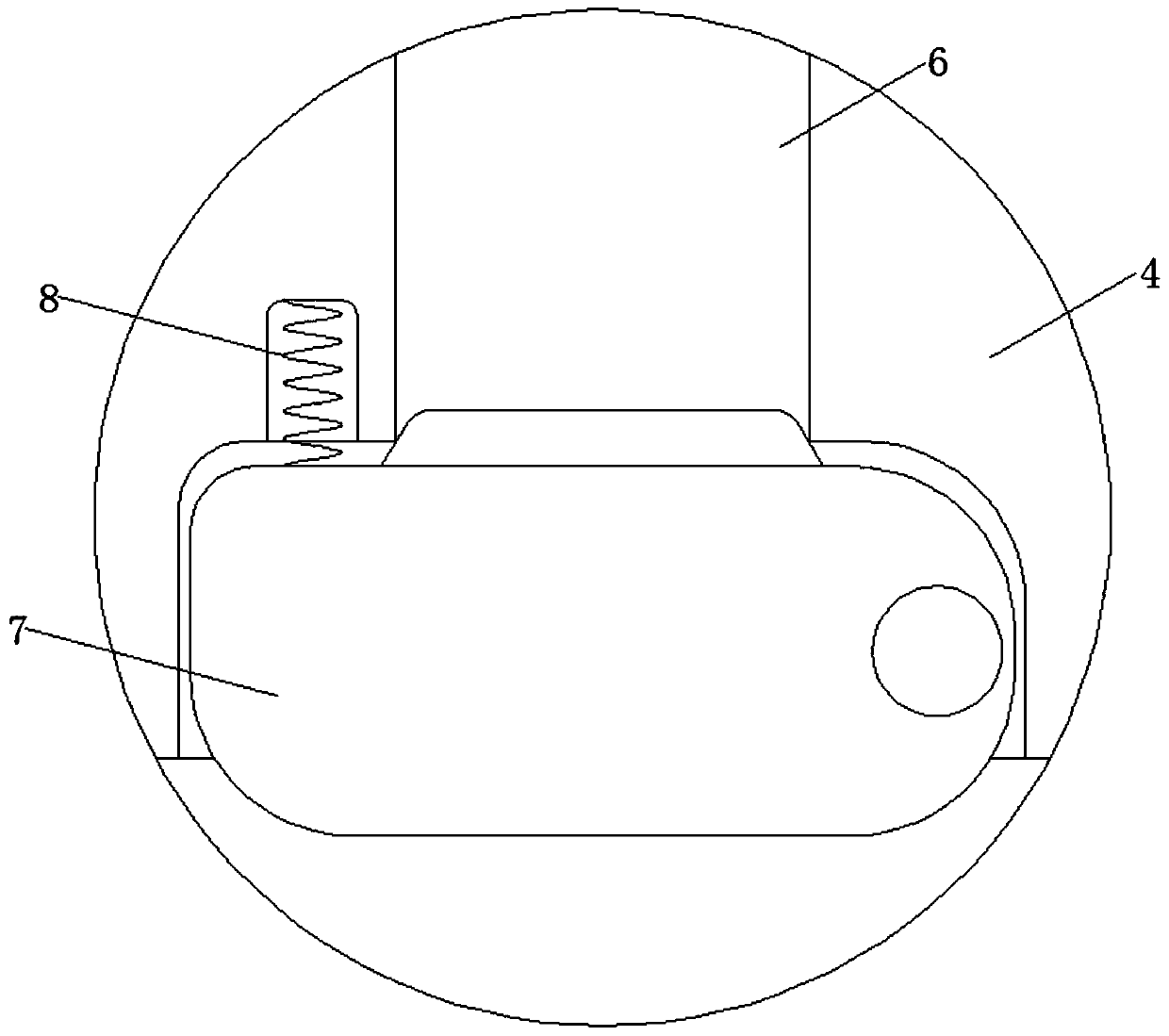
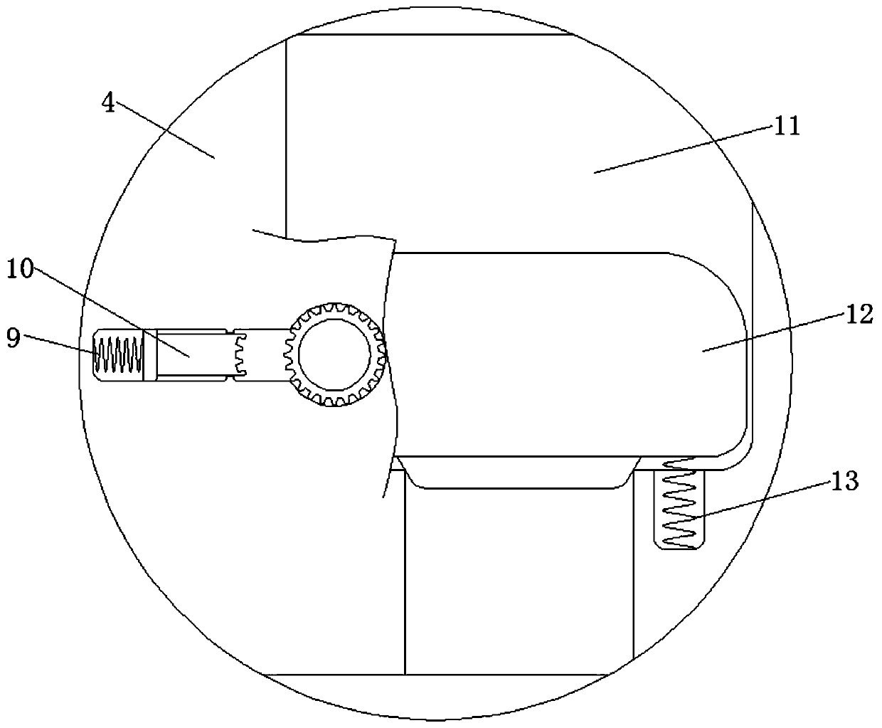
[0020] see Figure 1-4 , a pneumatic and magnetically controlled retractable speed bump, including a roadbed 1, the roadbed 1 plays the role of fixing and installing various components, the top of the roadbed 1 is provided with a storage groove suitable for the speed bump 2 and the bottom of the roadbed 1 is opened There is an installation groove compatible with the gas storage tank 14, the material of the speed bump 2 is hard rubber material and the width of ...


PUM


Abstract

The invention discloses a pneumatic and magnetically-controlled retractable deceleration strip, and relates to the technical field of intelligent transportation. The pneumatic and magnetically-controlled retractable deceleration strip includes a roadbed, the top of the roadbed is movably connected with a deceleration strip; the bottom of the deceleration strip is fixedly connected with a first spring fixedly connected with the inner bottom wall of the top of the roadbed. The bottom of the deceleration strip is fixedly connected with a piston block through a connecting rod, the middle of the piston block is fixedly connected with a magnetic control device, the bottom of the left side of the piston block is provided with an air inlet penetrating and extending to the top of the piston block,and the left side of the bottom of the piston block is rotationally connected with a first plug. According to the pneumatic and magnetic control retractable deceleration strip, the first spring is matched with the piston block for use; when a vehicle slowly passes through the deceleration strip, the piston block slowly moves downwards, meanwhile, gas in the gas storage tank is slowly released, therelease speed can be adjusted according to the limited speed, and therefore the pneumatic contraction effect is achieved, when a vehicle slowly passes, the deceleration strip can be contracted into aroadbed, the bumping feeling of the vehicle is effectively reduced, and the comfort degree of passengers is increased.

Description

technical field [0001] The invention relates to the technical field of intelligent transportation, in particular to a pneumatic and magnetically controlled retractable speed bump. Background technique [0002] Intelligent transportation is the development direction of the future transportation system. It is an intelligent transportation system established by effectively integrating advanced information technology, data communication transmission technology, electronic sensing technology, control technology and computer technology into the entire ground traffic management system. It is a real-time, accurate and efficient comprehensive transportation management system that plays a role in a wide range and in all directions. [0003] The speed bumps on the road have the effect of reminding passing vehicles to slow down, but most of the current speed bumps are made of hard rubber. When the current speed bumps are used, they often cause a lot of inconvenience. For example, when t...

Claims


Application Information

Patent Timeline
Patent Type & Authority Applications(China)
IPC IPC(8): E01F9/529
CPCE01F9/529
Inventor 解波
Owner 苏州澎澄企业管理有限公司
Why Eureka
Try Eureka