Road speed reducing device utilizing centrifugal force to control vehicle speed

A deceleration device and centrifugal force technology, applied in the directions of roads, roads, road signs, etc., can solve the problems of reducing vehicle comfort, bumps, and contrary to safe driving, and achieve the purpose of reducing bumpiness, improving comfort, and improving practicability. Effect

Inactive Publication Date: 2020-11-10
吴崇文
View PDF5 Cites 1 Cited by
  • Summary
  • Abstract
  • Description
  • Claims
  • Application Information

AI Technical Summary

Problems solved by technology

[0003] The current roads are often equipped with some roadblocks with specific functions. For example, there are roadblocks reminding deceleration and anti-retrograde on the current roads, mainly to prevent vehicles from driving illegally. Most of the current deceleration devices are rubber belts. , mainly because the vehicle feels the bumps when passing, thereby reminding it to slow down, but when the vehicle passes at a slow speed, bumps will also occur, which reduces the comfort of the vehicle and is contrary to the original intention of safe driving

Method used


Image

  • Road speed reducing device utilizing centrifugal force to control vehicle speed
  • Road speed reducing device utilizing centrifugal force to control vehicle speed
  • Road speed reducing device utilizing centrifugal force to control vehicle speed

Examples


Embodiment Construction

[0019] The following will clearly and completely describe the technical solutions in the embodiments of the present invention with reference to the accompanying drawings in the embodiments of the present invention. Obviously, the described embodiments are only some, not all, embodiments of the present invention. Based on the embodiments of the present invention, all other embodiments obtained by persons of ordinary skill in the art without making creative efforts belong to the protection scope of the present invention.

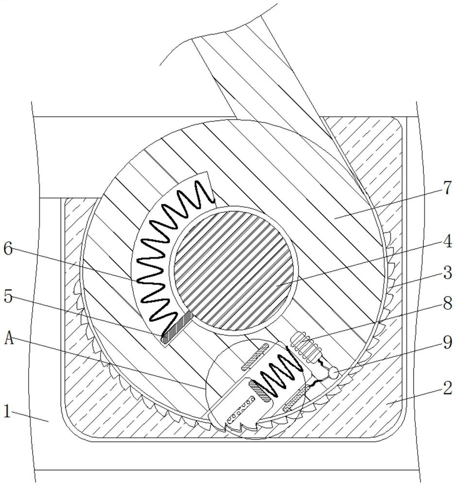
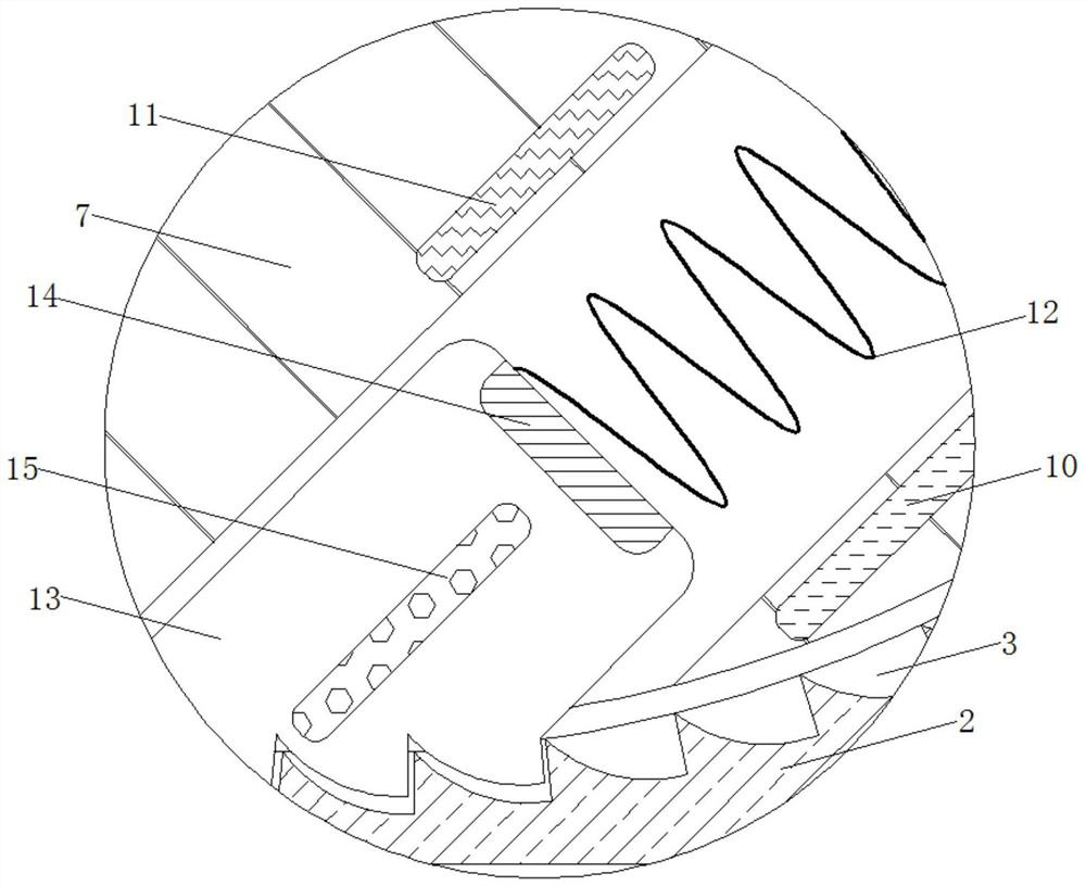
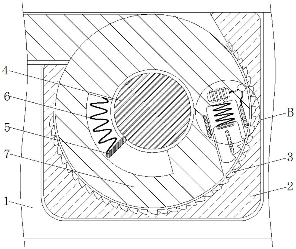
[0020] see Figure 1-4 , a road deceleration device that uses centrifugal force to control the speed of the vehicle, including a road 1, the road 1 plays the role of fixing the mounting seat 2, the material of the road 1 is a hard high-strength material and the depth of the road 1 is greater than the height of the mounting seat 2 The material of the mounting seat 2 is a hard high-strength material and the shape of the mounting seat 2 is a cuboid. The top of th...


PUM


Abstract

A road speed reducing device utilizing centrifugal force to control vehicle speed relates to the technical field of roads and comprises a road, a mounting seat is movably connected to the top of the road, uniformly distributed clamping grooves are formed in the inner wall of the mounting seat, a rotating shaft is fixedly connected to the middle of the mounting seat, and a connecting plate is fixedly connected to the outer side of the rotating shaft. The outer side of the connecting plate is fixedly connected with a first spring. According to the road speed reduction device for controlling thevehicle speed through the centrifugal force, through cooperative use of the clamping blocks and the clamping grooves, when a vehicle rapidly passes through the speed reduction device, the rotating blocks rapidly rotate and generate large centrifugal force, the clamping blocks are thrown out, the clamping grooves are connected in a clamped mode, rotation of the rotating blocks is limited, the vehicle feels jolt, and the vehicle is reminded to decelerate; when a vehicle slowly passes, the rotating block can automatically rotate and contract into the ground, the top of the rotating block is madeto be flush with the top of a road, and therefore the vehicle can stably pass, the bumping feeling of the vehicle is effectively reduced, and the comfort degree when the vehicle passes is improved.

Description

technical field [0001] The invention relates to the technical field of roads, in particular to a speed reduction device for roads that uses centrifugal force to control vehicle speed. Background technique [0002] From the meaning of the word, the road is the infrastructure for various trackless vehicles and pedestrians; according to its use characteristics, it can be divided into highways, urban roads, country roads, factory and mine roads, forestry roads, examination roads, competition roads, automobile test roads, workshop passages and school roads etc. [0003] The current roads often have some roadblocks with specific functions during use. For example, there are roadblocks reminding deceleration and anti-retrograde roadblocks on the current roads, mainly to prevent vehicles from driving illegally. Most of the current deceleration devices are rubber belts. , mainly because the vehicle feels the bumps when passing, thereby reminding it to slow down, but when the vehicle ...

Claims


Application Information

Patent Timeline
Patent Type & Authority Applications(China)
IPC IPC(8): E01F9/529H01F7/08
CPCE01F9/529H01F7/08
Inventor 吴崇文
Owner 吴崇文
Why Eureka
Try Eureka