
Patient transfer wheeled bed

A bed car and patient technology, applied in the field of patient transfer bed car, can solve problems such as inability to tilt, inconvenient transportation, etc., to achieve the effect of improving comfort, reducing the probability of accidents, and extending the length

Inactive Publication Date: 2017-05-31
李艳霞
View PDF0 Cites 1 Cited by
  • Summary
  • Abstract
  • Description
  • Claims
  • Application Information

AI Technical Summary

Problems solved by technology

[0004] The present invention aims at the problem that the existing traditional flat bed car cannot be tilted, and many medical staff are required to cooperate when carrying the patient, which is inconvenient to carry and increases the burden on the medical staff, and provides a patient transfer bed car

Method used


Image

  • Patient transfer wheeled bed
  • Patient transfer wheeled bed

Examples


Embodiment 1

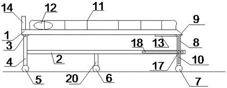
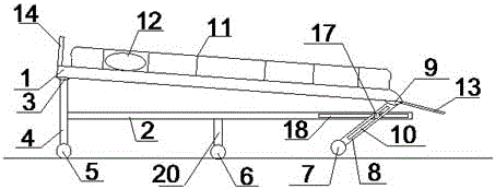
[0029] Such as figure 1 As shown, the structural diagram of the patient transfer bed vehicle includes a bed board 1, a bedside support frame 4, a bedside support frame 8 and a reinforcing rib 2, wherein one end of the bedside support frame 4 is connected to the bedside of the bed board 1 through the first movable part 3, The other end is connected with the first roller 5. One end of the bed end support frame 8 is movably connected with the bed end of the bed board 1 through the second movable part 9 , and the other end is connected with the second roller 7 , and the bed end support frame 8 is provided with a first chute 10 . The reinforcing rib 2 is located under the bed board 1, and a second chute 18 is arranged on it. One end of the reinforcing rib 2 is fixedly connected with the bedside support frame 4, and the other end passes through the fixing bolt passing through the first chute 10 and the second chute 18. 17 is connected with bed end support frame 8.

[0030] During ...

Embodiment 2

[0032] Such as figure 1 As shown in the schematic diagram of the structure of the patient transfer bed vehicle, based on the first embodiment, the reinforcing rib 2 is connected with a vertically downward auxiliary support frame 20 , and the other end of the auxiliary support frame 20 is connected with the auxiliary roller 6 .

Embodiment 3

[0034] Such as figure 1 As shown in the schematic diagram of the structure of the patient transfer bed vehicle, based on Embodiment 1, the bed board 1 is connected with a vertically upward limiting column 14 .


PUM


Abstract

The invention relates to the field of medical instruments, and discloses a patient transfer wheeled bed. The patient transfer wheeled bed is characterized in that a bed plate, bed head support frames, bed tail support frames and reinforcing ribs; one end of each bed head support frame is connected with a bed head of the bed plate through a first movable part, and the other end of each bed head support frame is connected with a first rolling wheel; one end of each bed tail support frame is movably connected with a bed tail of the bed plate through a second movable part, the other end of each bed tail support frame is connected with a second rolling wheel, and a first sliding groove is formed in each bed tail support frame; the reinforcing ribs are located under the bed plate, second sliding grooves are formed in the reinforcing ribs, one end of each reinforcing rib is fixedly connected with the corresponding bed head support frame, and the other end of each reinforcing rib is connected with the corresponding bed tail support frame by penetrating through fixing bolts of the corresponding first sliding groove and second sliding groove. According to the structure, the patient transfer wheeled bed keeps stable, therefore a patient can lie flat on the wheeled bed, and medical staff can push the wheeled bed to transport the patient; after the wheeled bed reaches an assigned place, the patient transfer wheeled bed does not keep stable any more by loosening the fixing bolts, the patient can independently slide down the patient transfer wheeled bed or easily get down the wheeled bed with the help of the medical staff.

Description

technical field [0001] The invention relates to the field of medical equipment, in particular to a patient transfer bed vehicle. Background technique [0002] At present, hospitals often use traditional flat bed carts in the process of transferring patients. When patients get on and off the bed carts, medical staff need to help them. If some patients have fractures, erectile dysfunction and other problems, it is difficult for medical staff to help them. , need many people to carry the patient up and down, which undoubtedly increases the pain of the patient and increases the burden on the patient's family members and medical staff. [0003] Therefore need a kind of simple in structure, can realize tilting, be convenient to the patient transfer bed car of medical personnel carrying patient. Contents of the invention [0004] The present invention aims at the problem that the existing traditional flat bed car cannot be tilted, and many medical staff are required to cooperate...

Claims


Application Information

Patent Timeline
IPC IPC(8): A61G1/02A61G1/04
CPCA61G1/02A61G1/04
Inventor 李艳霞
Owner 李艳霞
Learn More