Mixing equipment for coating material dilution

A technology for mixing equipment and coatings, applied in mixers, mixers with rotating stirring devices, dissolving, etc., can solve the problems of ineffective dilution and affecting the color of coatings, etc.

Active Publication Date: 2020-04-17
陕西龙义泽环保建材有限公司
View PDF12 Cites 5 Cited by
  • Summary
  • Abstract
  • Description
  • Claims
  • Application Information

AI Technical Summary

Problems solved by technology

[0005] In order to overcome the disadvantage that it is difficult for people to control the amount of diluent injected, if there is too much diluent, the color of the paint will be affected, and if the diluent is too small, the effect of dilution will not be obvious. Therefore, the technical problem of the present invention is: to provide a A kind of mixing equipment for paint dilution that can accurately control the injection amount of thinner to avoid too much or too little thinner

Method used


Image

  • Mixing equipment for coating material dilution
  • Mixing equipment for coating material dilution
  • Mixing equipment for coating material dilution

Examples


Embodiment approach 1

[0026] A mixing device for paint thinning, such as Figure 1-3 As shown, it includes a box frame 1, a stirring box 3, a storage box 4, an injection funnel 5, a discharge pipe 6, a rotary regulating valve 61, a sealing assembly 7, a quantitative feeding assembly 8 and a stirring assembly 9, and the box body There is a placement groove 2 on the left side of the top of the frame 1, and a mixing box 3 is installed on the right side of the top of the box frame 1 through bolts. It is semi-circular, the top of the material storage box 4 is connected to the liquid injection funnel 5, the bottom of the mixing box 3 is connected to the discharge pipe 6, the discharge pipe 6 is provided with a rotary regulating valve 61, and the right side of the stirring box 3 is installed with a sealing assembly 7. Quantitative feeding assembly 8 is installed in storage box 4, and stirring assembly 9 is installed at the bottom of stirring box 3.

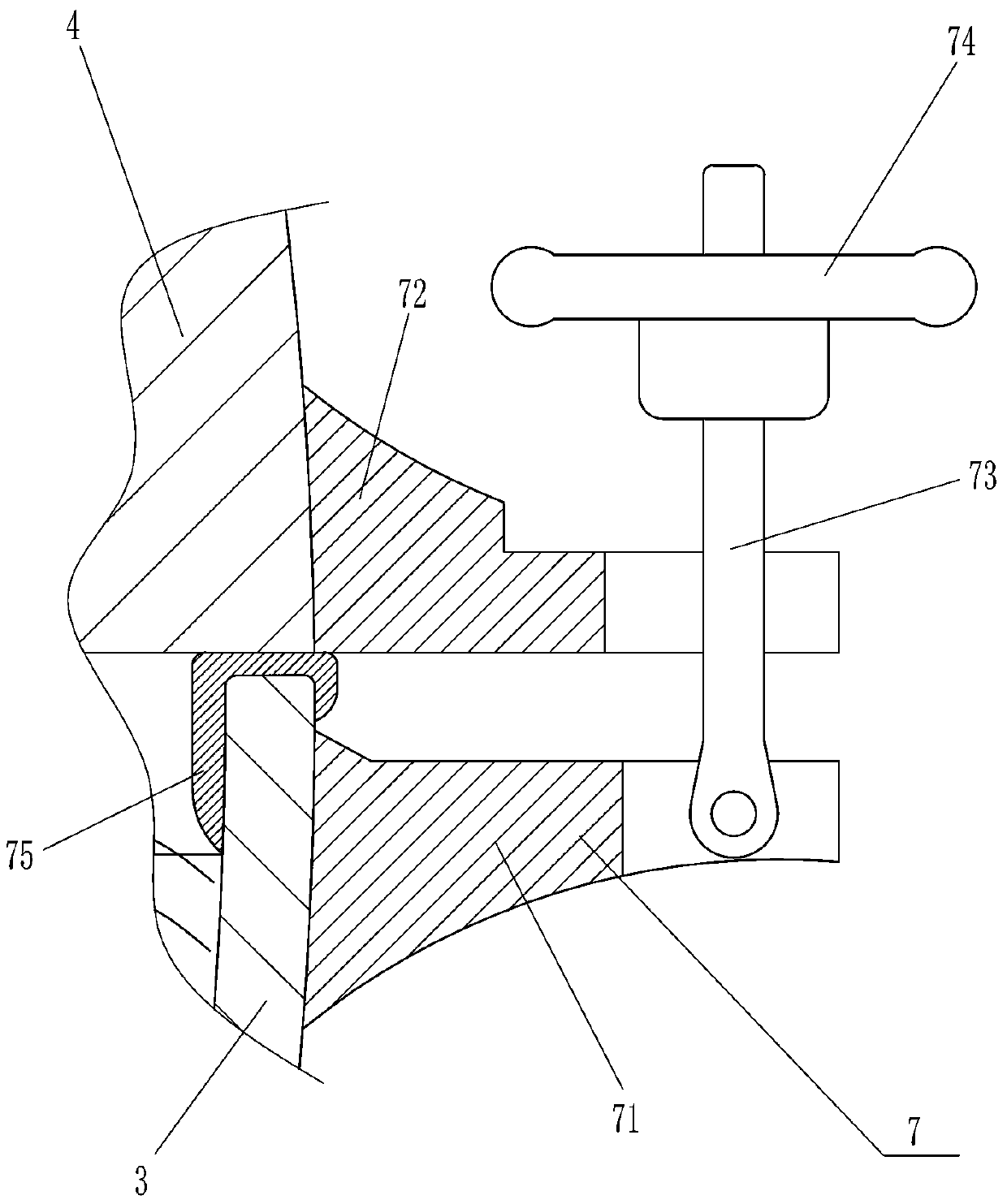
[0027] The sealing assembly 7 includes a first fixed b...

Embodiment approach 2

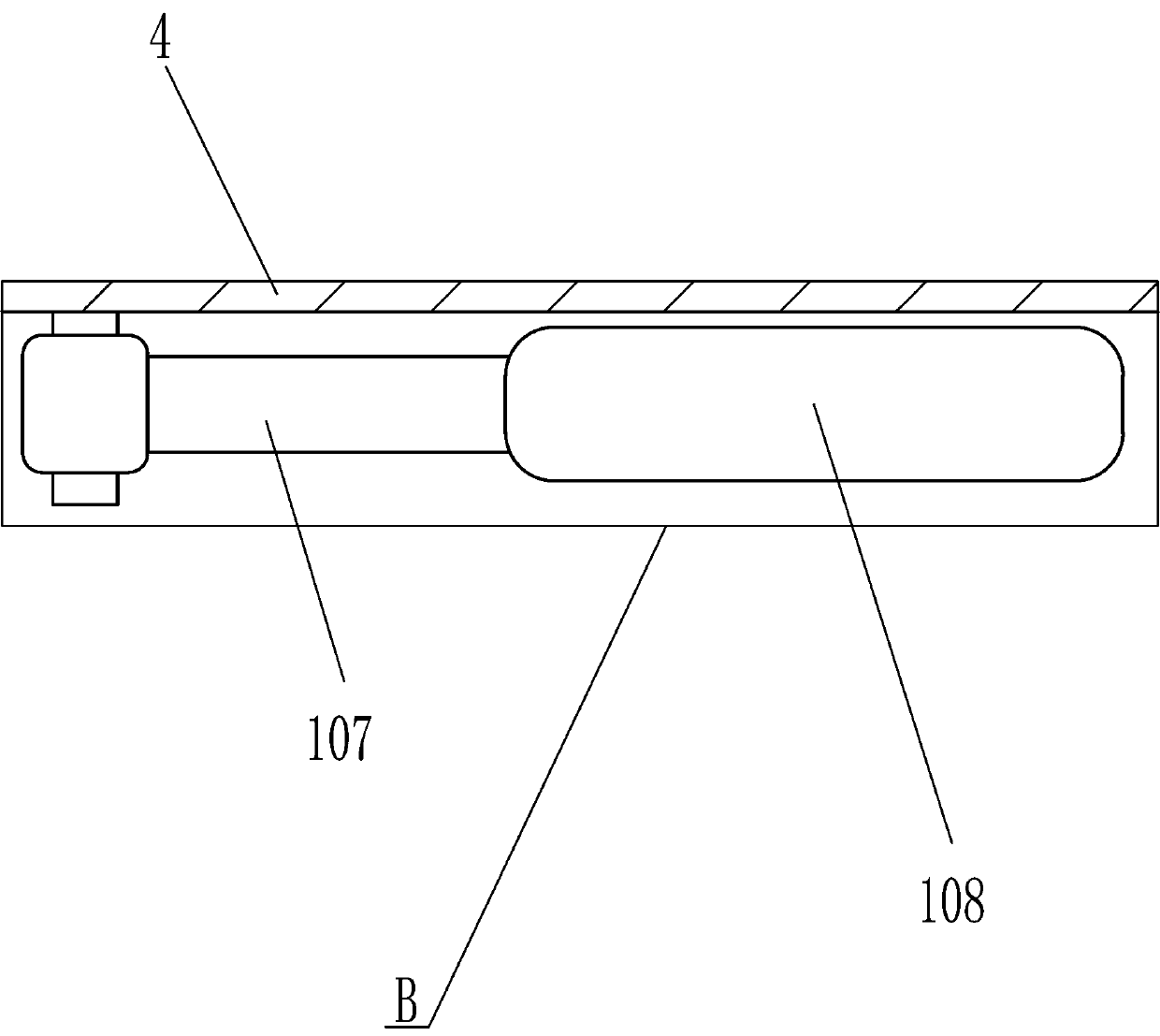
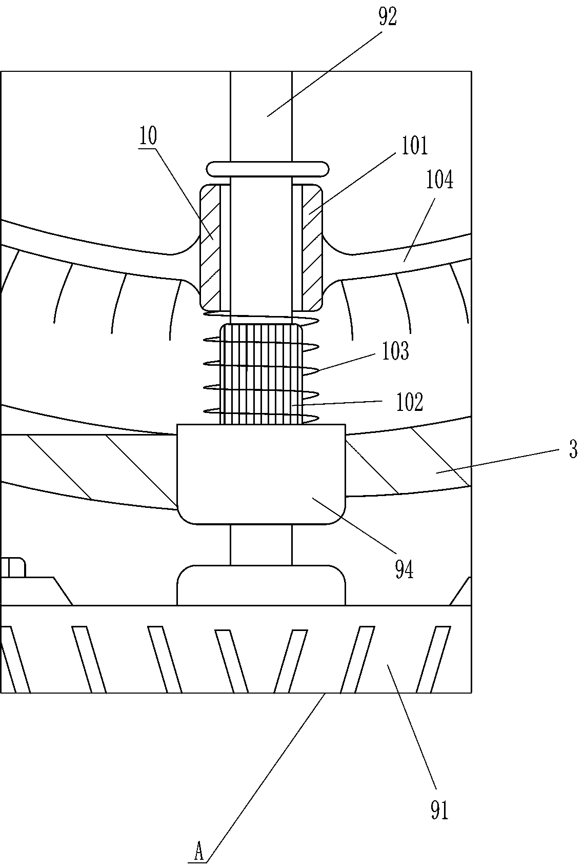
[0035] On the basis of Embodiment 1, if figure 1 , image 3 , Figure 4 and Figure 5 As shown, a cleaning mechanism 10 is also included, and the cleaning mechanism 10 includes a ring gear 101, a gear rod 102, a first spring 103, a brush rod 104, an oblique bracket 105, a contact rod 106, a hinged rod 107 and a contact plate 108. The rod 92 is covered with a gear ring 101, the lower part of the rotating rod 92 is connected with a gear rod 102, the bottom of the gear ring 101 is connected with a first spring 103, the gear rod 102 passes through the first spring 103, and the left and right sides of the gear ring 101 are connected with hair Brush rod 104, two hair brush rods 104 are arc-shaped, the inner side of hair brush rod 104 is connected with oblique support 105, is connected with contact rod 106 through bearing seat rotation type between two oblique support 105, storage box 4 bottom right The side is hingedly connected with a hinged rod 107 , and the right end of the hi...


PUM


Abstract

The invention relates to mixing equipment, particularly to mixing equipment for coating material dilution. The technical problem to be solved by the invention is how to provide mixing equipment used for coating material dilution and capable of accurately controling the injection amount of a diluent and preventing the diluent from being too much or too little. The mixing equipment comprises a box body frame, a stirring box and the like, wherein a placing groove for placing a container is formed in the box body frame, and the stirring box is fixedly connected to the box body frame. According tothe invention, a proper amount of a diluent can be injected into the stirring box through a quantitative feeding assembly, so that the injection amount of the diluent can be accurately controlled, andthe diluent is prevented from being too much or too little; the inner wall of the stirring box can be cleaned through a cleaning mechanism, so that the coating material is prevented from remaining inthe stirring box so as not to affect the next use; and the upward moving distance of a pull rod can be adjusted through an adjusting mechanism, so that a proper amount of the diluent can be sucked inaccurately.

Description

technical field [0001] The invention relates to a mixing device, in particular to a mixing device for paint dilution. Background technique [0002] Coatings are also called paints, which are used to coat the surface of objects for protection and decoration. Coatings belong to organic chemical polymer materials, and the formed coating film belongs to the type of polymer compounds. Modern coatings have gradually become a class of multifunctional materials. For engineering materials, when using paint, it is necessary to dilute the paint to reduce the viscosity of the paint so that it can be better coated on the object. [0003] In the prior art, for example, the patent with the publication number CN207012846U discloses a portable paint thinning device, which includes a base, the stirring frame is located in the inner cavity of the cylinder, and the outer side of the movable shaft is provided with a toothed plate. When working, people need to manually pour the thinner into the ...

Claims


Application Information

Patent Timeline
Patent Type & Authority Applications(China)
IPC IPC(8): B01F7/16B01F15/04B01F15/02B01F15/00
CPCB01F27/808B01F35/121B01F2035/351B01F35/75471B01F35/8822B01F2101/30
Inventor 陈国语
Owner 陕西龙义泽环保建材有限公司
Why Eureka
Try Eureka