Sealing machine

A sealing machine and rack technology, applied in the field of sealing machines for ice packs, can solve the problems of inconvenient repair, large floor space, complicated installation, etc., and achieve the effects of easy-to-understand structure, easy procurement, and convenient maintenance.

Active Publication Date: 2017-05-24
QINGDAO UNIV
View PDF5 Cites 7 Cited by
  • Summary
  • Abstract
  • Description
  • Claims
  • Application Information

AI Technical Summary

Problems solved by technology

However, the device structure of the filling and filling modules of the existing sealing machines is generally larger, the structure is more complex and relies too much on the circuit system, resulting in a large footprint and complicated installation, and it is difficult to accurately control the operation of small packaging bags. Amount of feed
At the same time, the structure of the detection device used in the detection of defective products is also relatively complicated, and it is not easy to repair after a fault occurs

Method used


Image

  • Sealing machine
  • Sealing machine
  • Sealing machine

Examples


Embodiment Construction

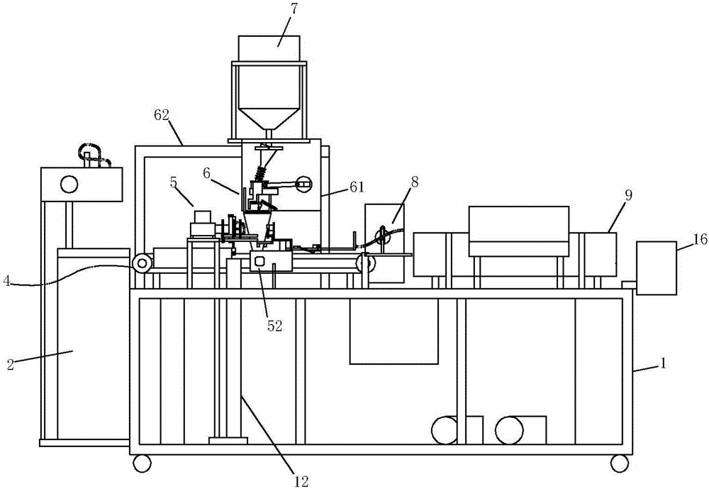
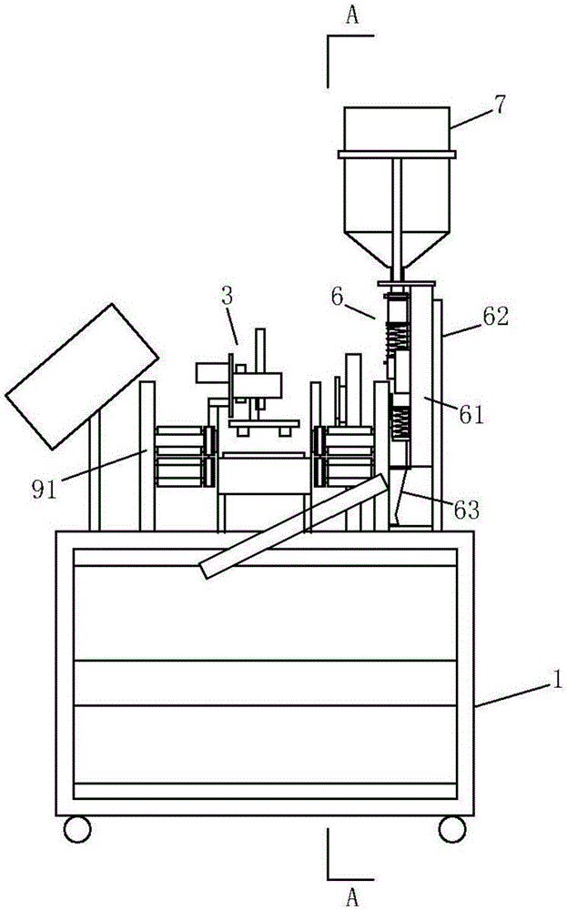
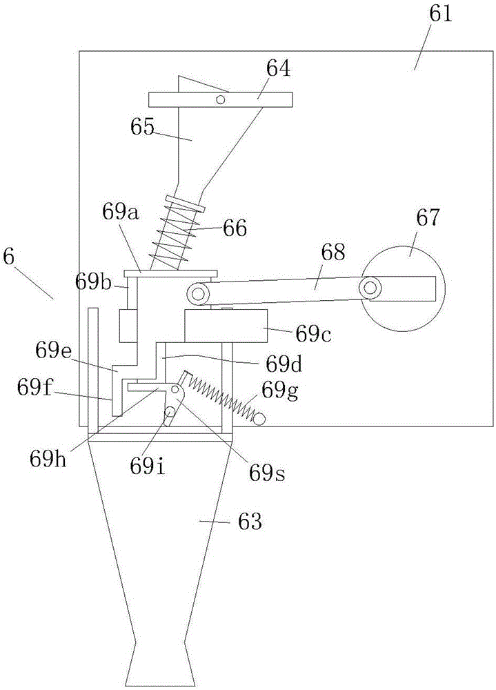
[0030] The sealing machine as shown in the accompanying drawings includes a frame 1 and a working device arranged on the frame 1 and composed of control, power supply, injection, conveying, hot pressing modules 9 and related auxiliary modules, containing packaging bags 100 The first material box 2 is set on one side of the frame 1, the packaging bag 100 in the first material box 2 is transported to the delivery module 4 by the delivery device, and the resin delivery module 6 and the water injection bag delivery module 5 take the delivery module 4 as the axis Symmetrically arranged on the frame 1, the hot pressing module 9 is arranged at the end of the delivery module 4, the resin delivery module 6 includes a support frame 62 arranged on the frame 1, and a first mounting plate fixed on the support frame 62 61. The control and valve assembly arranged on the first installation plate 61, the resin storage tank 7 arranged above the first installation plate 61 and the discharge nozzl...


PUM


Abstract

The invention relates to a sealing machine. The sealing machine comprises a rack as well as a working device which is arranged on the rack, and consists of a control module, a power supply module, an injection module, a conveying module, a hot-pressing module and related auxiliary modules, wherein a resin conveying module and a water injection bag conveying module are symmetrically arranged on the rack by taking the conveying module as an axis; the hot-pressing module is arranged at the tail end of the conveying module which adopts a transmission chain type conveying mode, and comprises a first supporting plate fixedly arranged on the rack as well as transmitting chains arranged at the two sides of the first supporting plate; bumps which are bulged outwards are arranged on the transmitting chains in the forms of arrays; a distance between adjacent bumps is determined by a packaging bag; a second mounting plate is arranged on a supporting frame fixedly connected with the rack; a movable rod can be arranged on the second mounting plate in a sliding mode, and an upper vacuum sucking disc is arranged on the movable rod; a space for allowing a lower vacuum sucking disc to extend out is formed in the first supporting plate; and the upper vacuum sucking disc and the lower vacuum sucking disc are coaxially arranged between the resin conveying module and the water injection bag conveying module.

Description

technical field [0001] The invention relates to a machine for sealing packages, in particular to a machine for sealing ice bags. Background technique [0002] The sealing machine belongs to the packaging machinery. After the material is loaded into the packaging bag, the sealing module of the packaging bag is heated to soften the film, and then it is cooled and bonded to achieve the purpose of sealing. However, the device structure of the filling and filling modules of the existing sealing machines is generally larger, the structure is more complex and relies too much on the circuit system, resulting in a large footprint and complicated installation, and it is difficult to accurately control the operation of small packaging bags. Amount of feed. Simultaneously, the structure of the detection device used in the detection of defective products is also relatively complicated, and it is inconvenient to repair after a failure occurs. Contents of the invention [0003] In orde...

Claims


Application Information

Patent Timeline
Patent Type & Authority Applications(China)
IPC IPC(8): B65B51/16
CPCB65B51/16
Inventor 徐世许张厚爱王伟郑建芬王汉萍王现富
Owner QINGDAO UNIV
Why Eureka
Try Eureka