Telescopic mutual inductance current polarity testing device

A technology of polarity testing and sensing current, which is applied in measuring devices, electrical winding testing, measuring electrical variables, etc. It can solve problems such as dropping, time-consuming and labor-intensive, and safety cannot be guaranteed, and achieves convenient operation, suitable for popularization and application, and convenient connection with the effect of lifting

Active Publication Date: 2020-05-08
GUIZHOU POWER GRID CO LTD
View PDF13 Cites 6 Cited by
  • Summary
  • Abstract
  • Description
  • Claims
  • Application Information

AI Technical Summary

Problems solved by technology

[0002] When the power grid configuration is accepted for new, rebuilt and expanded intervals, it is necessary to conduct a polarity test on the secondary circuit of the current transformer to ensure that the wiring is correct. At present, the commonly used method is for the staff to climb onto the transformer and overlap the wires respectively. To the primary winding P1 and P2 side of the transformer, and then connect the wires to the dry battery pack for flashing and co-current, and then confirm the direction of the secondary current at the interval terminal box with a pin-type multimeter, and the staff climbs to the transformer It is time-consuming and labor-intensive, and there is a risk of falling, and high-altitude wire bonding is required, so safety cannot be guaranteed

Method used


Image

  • Telescopic mutual inductance current polarity testing device
  • Telescopic mutual inductance current polarity testing device
  • Telescopic mutual inductance current polarity testing device

Examples


Embodiment Construction

[0023] The following will clearly and completely describe the technical solutions in the embodiments of the present invention with reference to the accompanying drawings in the embodiments of the present invention. Obviously, the described embodiments are only some, not all, embodiments of the present invention. All other embodiments obtained by persons of ordinary skill in the art based on the embodiments of the present invention belong to the protection scope of the present invention.

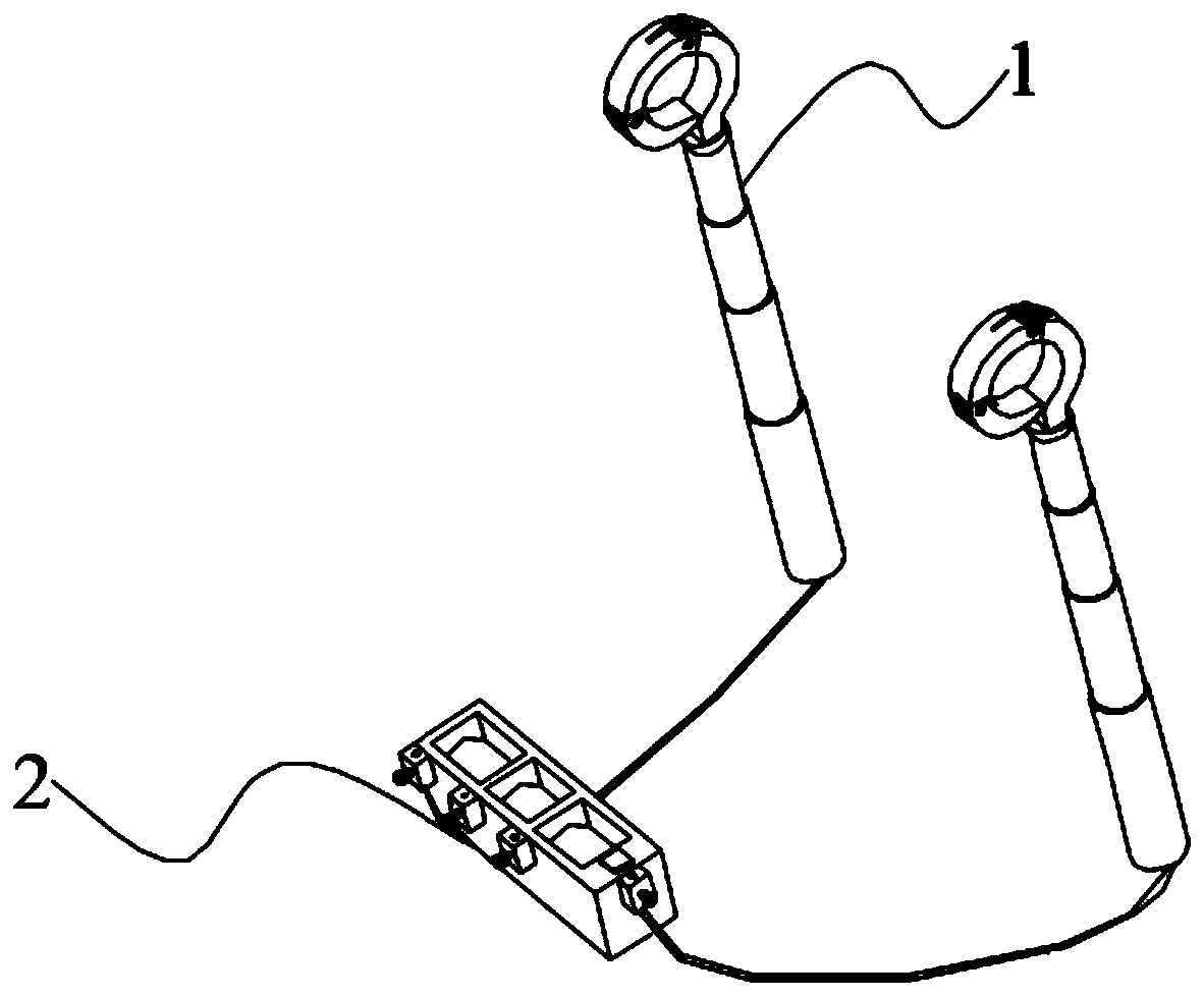
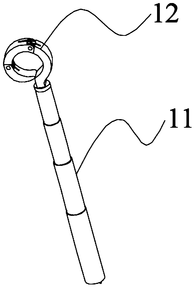
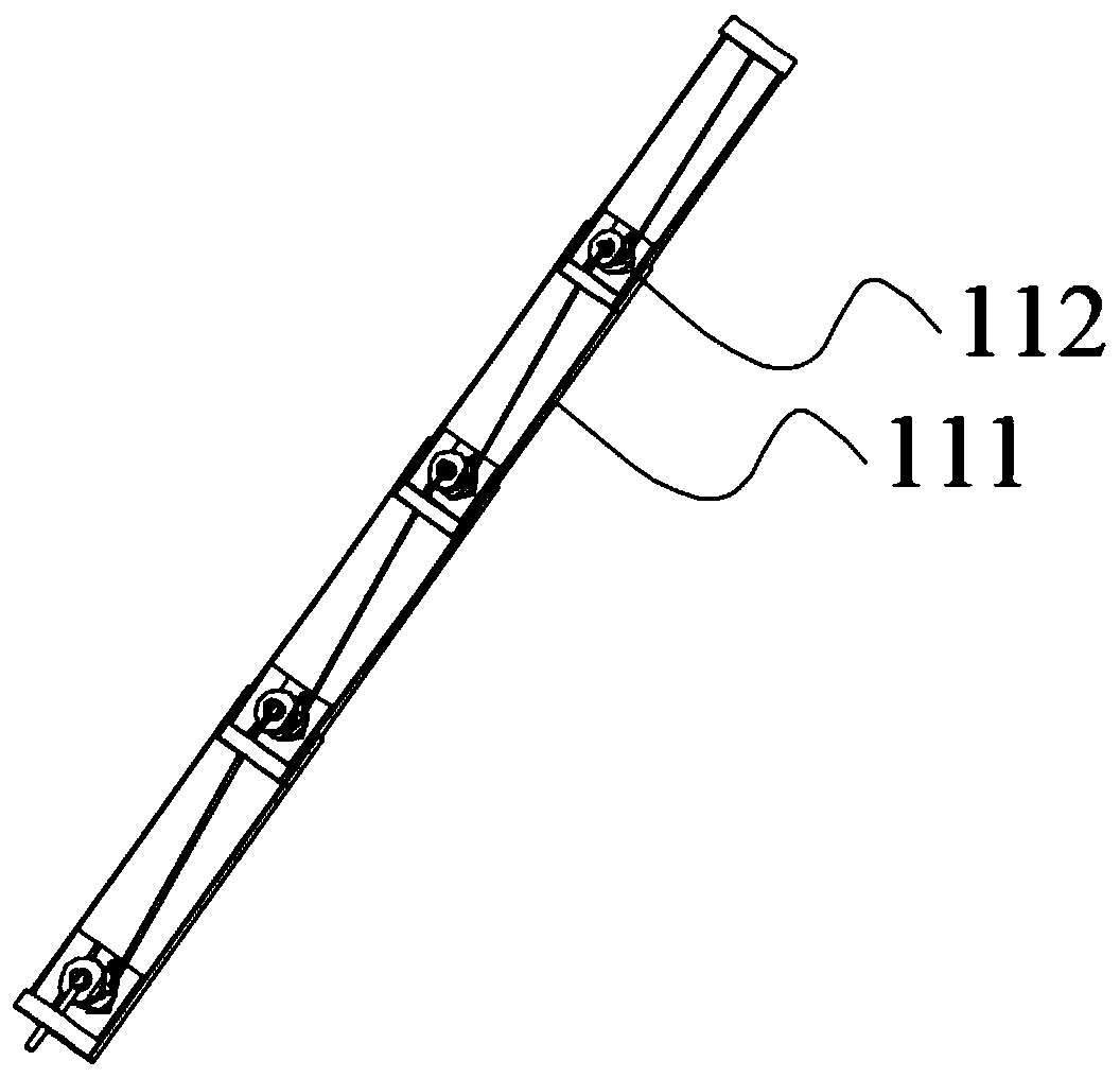
[0024] As shown in the figure, the present invention discloses a telescopic mutual inductance current polarity test device, which is characterized in that it includes: a lapping arm 1 and a battery box 2, and the lapping arm 1 is fixed by a telescopic rod 11 and a gripper 12 connected, the telescopic rod 11 is pierced with a wire, and the two ends of the wire are respectively electrically connected to the handle 12 and the battery box 2, and the handle 12 includes: a first connecting part 121 ...


PUM


Abstract

The invention relates to the technical field of current mutual inductance polarity testing, in particular to a telescopic mutual-inductance current polarity testing device comprising a lap joint arm and a battery box. The lap joint arm is formed by fixedly connecting a telescopic rod and a gripper. A wire is arranged in the telescopic rod in a communicating mode. The two ends of the wire are electrically connected with the gripper and the battery box respectively. The gripper comprises a first connecting part, a second connecting part and a fixing head, the first connecting part is rotationally connected with the second connecting part, the second connecting part is rotationally connected with the fixing head, the bottom of the fixing head is electrically connected with the wire, and the first connecting part, the second connecting part and the fixing head form a circular ring structure. Therefore, problems that time and labor are wasted when a worker climbs to a mutual inductor, falling risks exist, and safety cannot be guaranteed when high-altitude wire lap joint is conducted are solved.

Description

technical field [0001] The invention relates to the technical field of current mutual inductance polarity testing, in particular to a telescopic mutual inductance current polarity testing device. Background technique [0002] When the power grid configuration is accepted for new, rebuilt and expanded intervals, it is necessary to conduct a polarity test on the secondary circuit of the current transformer to ensure that the wiring is correct. At present, the commonly used method is for the staff to climb onto the transformer and overlap the wires respectively. To the primary winding P1 and P2 side of the transformer, and then connect the wires to the dry battery pack for flashing and co-current, and then confirm the direction of the secondary current at the interval terminal box with a pin-type multimeter, and the staff climbs to the transformer It is time-consuming and labor-intensive, and there is a risk of falling, and high-altitude wire bonding is also required, so safety...

Claims


Application Information

Patent Timeline
IPC IPC(8): G01R31/72G01R35/02
CPCG01R35/02
Inventor 张茂铧周斌杨万锦郑海涯杨程封杰周立波吴育腾何承涛钱程金贵红丁志敏
Owner GUIZHOU POWER GRID CO LTD
Why Eureka
Try Eureka