Refrigerating system

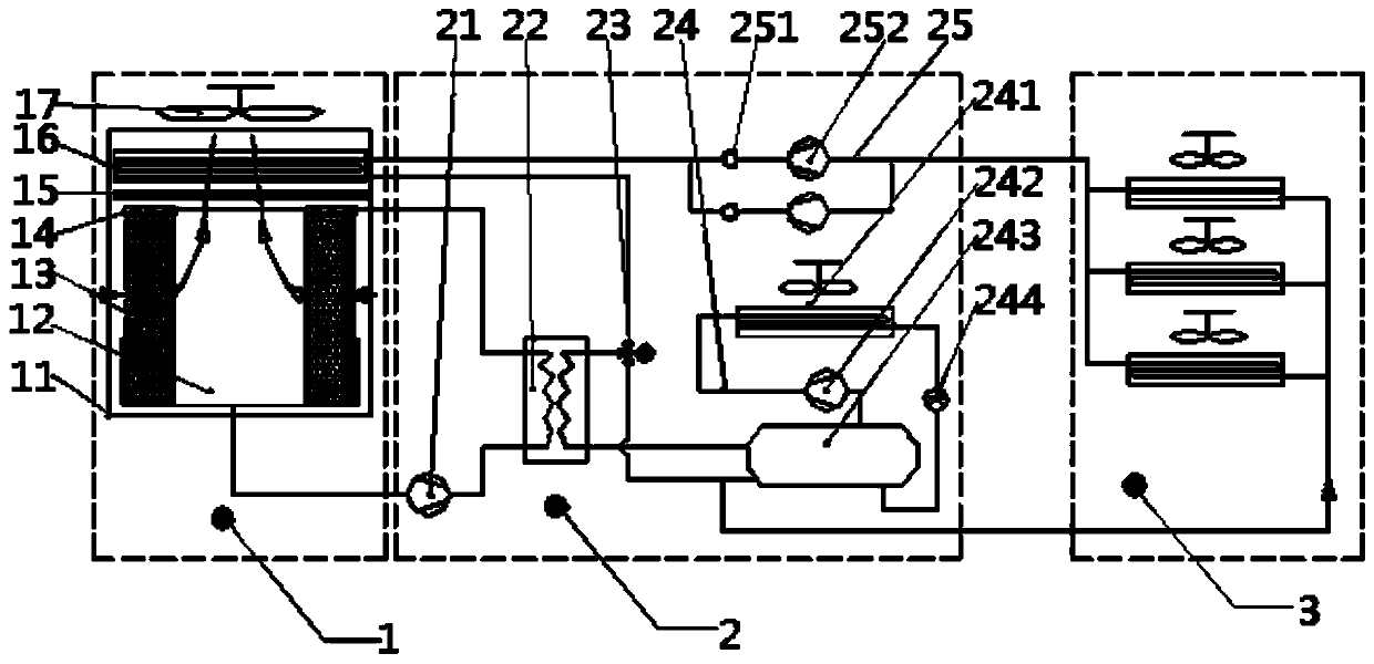
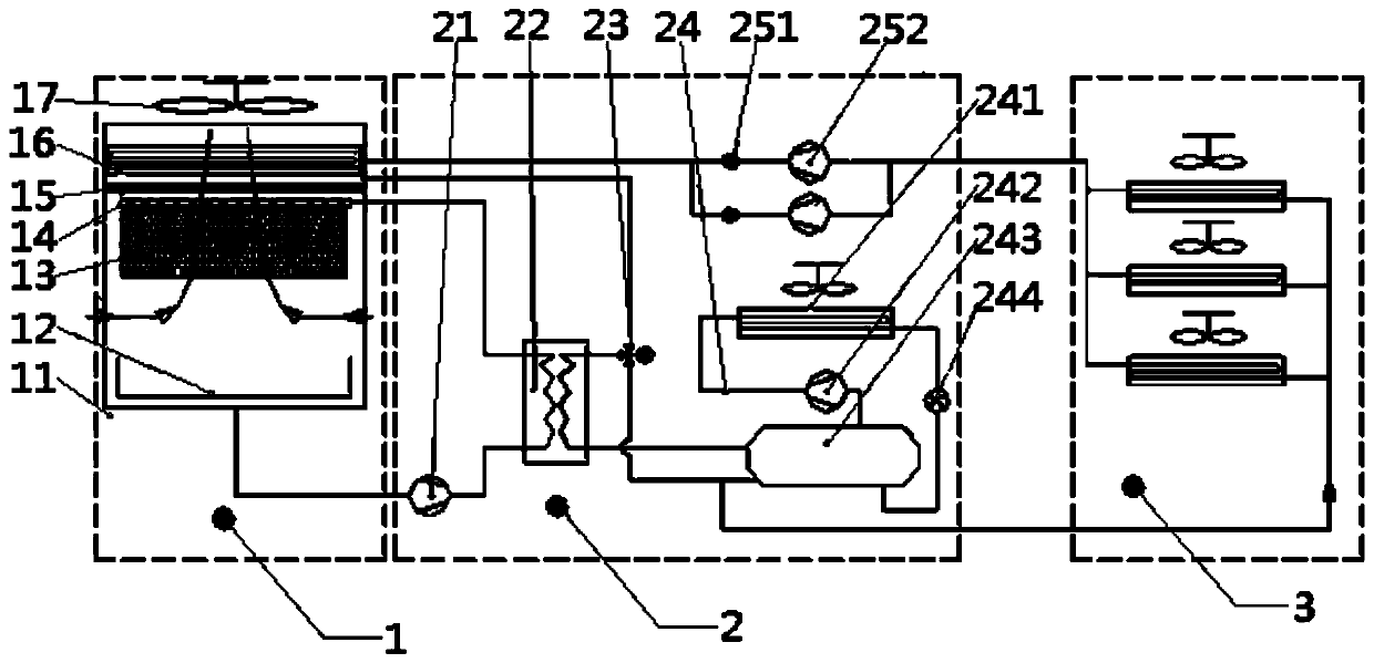
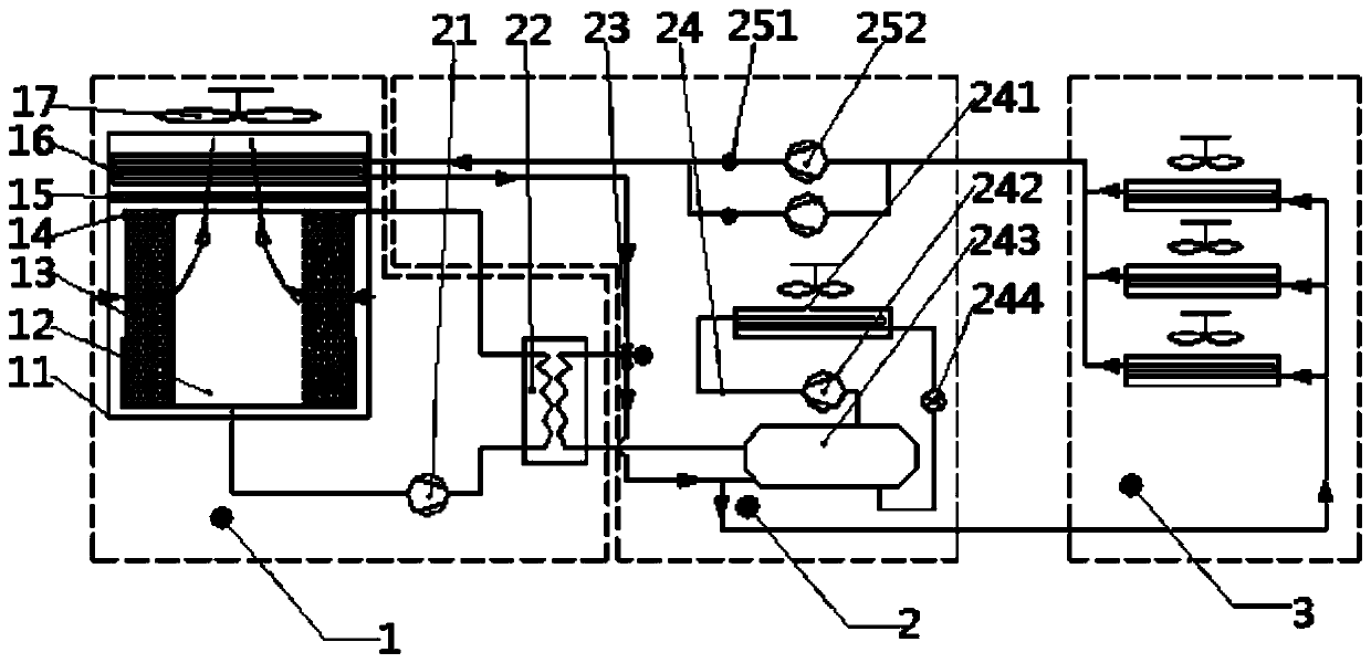
A refrigeration system, mechanical refrigeration technology, applied in air conditioning systems, household heating, space heating and ventilation details, etc., can solve the problem of increasing energy efficiency, only building against walls or top floors, and insufficient use of air cooling sources And other issues

Active Publication Date: 2020-06-02
HEBEI QINHUAI DATA CO LTD +1
View PDF9 Cites 0 Cited by
  • Summary
  • Abstract
  • Description
  • Claims
  • Application Information

AI Technical Summary

Problems solved by technology

[0009] However, direct evaporative cooling is affected by environmental factors. In bad weather, it is all switched to indoor circulation, and mechanical refrigeration needs to be fully equipped
This system introduces fresh air, and the computer room can only be built against the wall or on the top floor; indirect evaporative cooling fully isolates the indoor / outdoor air, but the air conditioner needs to introduce fresh air to cool the indoor airflow, so the computer room can only be built against the wall or on the top floor, and the cooling can be transported over long distances. The source needs long air ducts, and the system with large air resistance has high energy consumption; both the ethylene glycol system and the chilled water / plate exchange switching system require full mechanical refrigeration, and the cooling tower needs to be sprayed in winter, which is easy to freeze in northern regions; Type natural cold source refrigeration system, direct evaporative cooling / fresh air for supplementary cooling in summer, can not control the humidity and cleanliness of the computer room, the ethylene glycol system running in winter has no effect in summer, and only increases the wind resistance of the outdoor airflow to the whole system energy efficiency
The water for evaporative cooling in this system has been fully utilized, but the air cooling source after evaporative cooling has not been fully utilized

Method used


Image

  • Refrigerating system
  • Refrigerating system
  • Refrigerating system

Examples


Embodiment Construction

[0055] The following will clearly and completely describe the technical solutions in the embodiments of the present invention with reference to the accompanying drawings in the embodiments of the present invention. Obviously, the described embodiments are only some, not all, embodiments of the present invention. Based on the embodiments of the present invention, all other embodiments obtained by persons of ordinary skill in the art without making creative efforts belong to the protection scope of the present invention.

[0056] The core of the present invention is to provide a refrigeration system that does not need to be sprayed in winter, can reduce maintenance requirements, and can make full use of natural cold sources to reduce the specific gravity of mechanical refrigeration and improve the energy efficiency of the system.

[0057] In order to enable those skilled in the art to better understand the solution of the present invention, the present invention will be further d...


PUM


Abstract

The invention discloses a refrigerating system. The refrigerating system comprises a cooling medium, a tail end, an outdoor cooler, a heat exchanger and a cold supplementing system module, wherein thetail end is used for providing heat exchange for the cooling medium and indoor air to reduce the indoor air temperature; the outdoor cooler is connected with the tail end and used for cooling the cooling medium through outdoor air; the heat exchanger is connected with the outdoor cooler and used for cooling the cooling medium through outdoor cooling water; and the cold supplementing system moduleis connected with the heat exchanger and used for cooling the cooling medium through mechanical refrigeration. According to the refrigerating system, outdoor cooling adopts evaporative cooling, the system supplements through the mechanical refrigeration, winter operation adopts the outdoor cooler for cooling, spraying is not needed, the maintenance requirements can be reduced, natural cold sources can further be sufficiently utilized, and thus the proportion of the mechanical refrigeration can be reduced and the energy efficiency of the system is improved.

Description

technical field [0001] The invention relates to the technical field of air conditioning and refrigeration, in particular to a refrigeration system. Background technique [0002] At present, the total energy consumption of data centers accounts for about 2% of the total energy consumption of the whole society, and the energy saving and emission reduction of data centers has become a key point of attention. For example, a typical PUE1.92 data center air-conditioning system accounts for about 26% of the energy consumption, and a PUE1.3 data center air-conditioning system consumes 17.5% of the energy consumption. When it is not possible to upgrade IT equipment, the air conditioning system is a priority. The energy saving of air conditioning system is the core of data center energy saving, and it is also an important way to reduce the energy consumption of data center, and it is the link with the greatest energy saving potential of data center. It can be said that whether the P...

Claims


Application Information

Patent Timeline
Patent Type & Authority Applications(China)
IPC IPC(8): F24F5/00F24F13/30
CPCF24F5/0035F24F5/001F24F13/30
Inventor 居静王剑陈云伟吴刚王铁旺陶锴王前方
Owner HEBEI QINHUAI DATA CO LTD
Why Eureka
Try Eureka