Bottle cap riveting equipment

A bottle cap and riveting technology, which is applied in metal processing equipment, capping, feeding devices, etc., can solve problems such as unguaranteed product quality, substandard product quality, and hidden safety hazards, and achieves small footprint, convenient operation, and The effect of ensuring stability

CN111496122APending Publication Date: 2020-08-07江苏长江盖业有限公司
0 Cites 0 Cited by

Patent Information

Authority / Receiving Office
CN · China
Patent Type
Applications(China)
Current Assignee / Owner
Publication Date
2020-08-07

Smart Images

  • Figure 1
    Figure 1
  • Figure 2
    Figure 2
  • Figure 3
    Figure 3
Patent Text Reader

Abstract

The invention provides bottle cap riveting equipment. The equipment comprises a rack, a rotating disc rotatably mounted on the center position of the rack, multiple bottle cap clamping devices sequentially mounted on the edge of the rotating disc in the circumferential direction of the rotating disc, a bottle cap loading mechanism, a bottle cap rotating positioning mechanism, a pull ring strip loading mechanism, a bottle cap pull ring riveting mechanism and a bottle cap discharging mechanism, wherein the bottle cap loading mechanism, the bottle cap rotating positioning mechanism, the pull ringstrip loading mechanism, the bottle cap and pull ring riveting mechanism and the bottle cap discharging mechanism are mounted on the periphery position of the rack, the bottle cap loading mechanism is used for conveying a bottle cap body to the bottle cap clamping device, the bottle cap rotating positioning mechanism is used for rotating a bottle cap body clamped on the bottle cap clamping deviceto enable a riveting protrusion to be positioned on a reserved position, the pull ring strip loading mechanism and the bottle cap pull ring riveting mechanism are correspondingly mounted, the pull ring strip loading mechanism is used for conveying a pull ring strip to the bottle cap pull ring riveting mechanism, the bottle cap pull ring riveting mechanism is used for separating a pull ring from the pull ring strip and riveting a riveting hole portion and the riveting protrusion to form a bottle cap, and the bottle cap discharging mechanism is used for falling off the bottle cap from the bottle cap clamping device.
Need to check novelty before this filing date? Find Prior Art

Description

technical field

[0001] The invention belongs to the technical field of bottle cap processing equipment, and in particular relates to a bottle cap riveting device. Background technique

[0002] The bottle cap is used as the sealing part of the common beverage bottle and other containing bottles. In order to facilitate the user to open it, the manufacturer usually sets a pull ring on the top wall of the bottle cap body to assist the opening of the bottle cap, so that the user does not need to use tools. Bottles can be opened. For this reason, a riveting protrusion is provided on the top wall of the bottle cap body, and a riveting hole matching the riveting protrusion is provided on the pull ring, and the riveting protrusion and the riveting hole are riveted together by riveting technology to form a bottle cap finished product. When assembling, the main body of the bottle cap needs to be clamped and fixed first, then the riveting hole on the pull ring is aligned with the rive...

Examples

Embodiment Construction

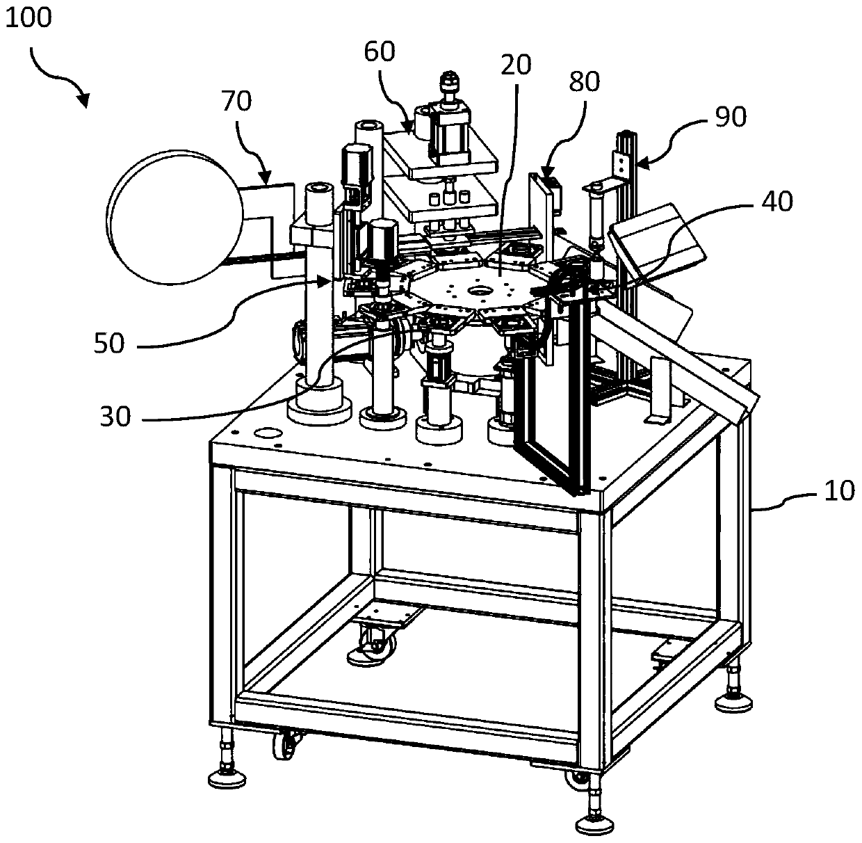
[0035] The idea, specific structure and technical effects of the present invention will be further described below in conjunction with the accompanying drawings, so as to fully understand the purpose, characteristics and effects of the bottle cap riveting equipment of the present invention.

[0036]

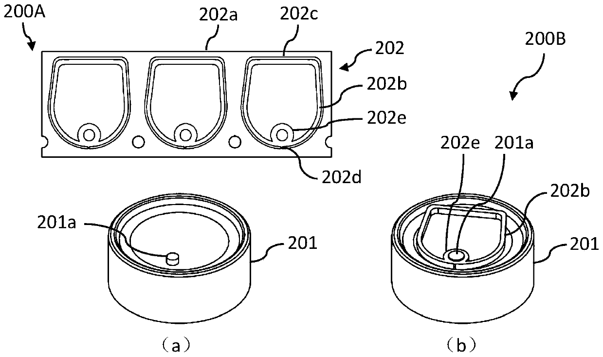
[0037] figure 1 It is a structural schematic diagram of a semi-finished bottle cap and a finished bottle cap in an embodiment of the present invention.

[0038] Such as figure 1 As shown, the bottle cap semi-finished product 200A includes a bottle cap body 201 and a pull ring belt 202 .

[0039] The bottle cap main body 201 is in the shape of a cylinder, and the edge of its top wall is provided with a riveting protrusion 201a.

[0040] The pull-tab strap 202 has a strap body 202a and a plurality of pull-tabs 202b.

[0041] The strap main body 202a is provided with a plurality of pull ring strap openings 202c arranged in sequence along its length direction and respectively ma...