Using method of spherical workpiece cutting machining device

A cutting and workpiece technology, applied in the field of workpiece processing machinery and equipment, can solve the problems of difficult tool head machining, cumbersome machining process, inability to meet the large-scale production and processing of shaft-shaped spherical workpieces, etc., and achieves reasonable structural design and machining automation. High degree, to achieve the effect of automatic spherical cutting

Inactive Publication Date: 2020-08-14
黄明珠
View PDF0 Cites 0 Cited by
  • Summary
  • Abstract
  • Description
  • Claims
  • Application Information

AI Technical Summary

Problems solved by technology

The shaft-shaped spherical workpiece is the main type of shaft-shaped workpiece. In the process of producing and processing the shaft-shaped spherical workpiece, the shaft-shaped spherical workpiece needs to undergo processing steps such as die-casting, grinding and drilling. The workpiece has various types of sizes, specifications and appearance shapes, especially when cutting the inner spherical surface of the shaft-shaped spherical workpiece with a hemispherical structure, the existing processing equipment is difficult to meet the production and processing needs of the shaft-shaped spherical workpiece. It is difficult for the clamping mechanism to clamp and fix the shaft-shaped spherical workpiece conveniently and efficiently and move it to the desired position, resulting in the inability of the shaft-shaped spherical workpiece to be accurately and smoothly transferred to the required processing station, which affects the efficiency and efficiency of the production and processing of the shaft-shaped spherical workpiece. Quality, the existing workpiece processing mechanism mainly adopts the clamping and fixing of the shaft-type spherical workpiece during the production and processing of the shaft-type spherical workpiece, and adjusts the processing head according to the needs, so as to realize the production and processing of the shaft-type spherical workpiece , but due to the complex structure of the processing head and many driving mechanisms, it is difficult for the processing head to perform operations such as rotation and translation conveniently and smoothly according to the needs of the processing of the shaft-shaped spherical workpiece. After the shaft-shaped spherical workpiece is clamped and fixed, the station can be rotated and adjusted smoothly and accurately. Therefore, in the processing process of the existing shaft-shaped spherical workpiece, the processing process is extremely cumbersome, and the processing cycle is also long, which cannot meet the batch size of the shaft-shaped spherical workpiece. The existing cutting mechanism has complex structure and troublesome operation, it is difficult to smoothly cut the spherical workpiece, and the adjustment of the processing cutter head is troublesome, and the processing cutter head is difficult to adjust quickly and conveniently along the spherical surface of the workpiece, and the adjustment The accuracy is poor, which makes it difficult for the existing cutting mechanism to efficiently and accurately cut the shaft-shaped spherical workpiece according to the production and processing needs of the shaft-shaped spherical workpiece. During the production and processing of the existing shaft-shaped spherical workpiece, it is difficult to be convenient and smooth Therefore, the production and processing of spherical workpieces are mainly processed manually one by one. After the production and processing of the workpieces are completed, the processed workpieces also need to be manually unloaded one by one. It is difficult to realize the automatic transfer and feeding of shaft-shaped spherical workpieces. And return materials, the work intensity of workers is relatively high, it is difficult to realize the large-scale production and processing of spherical workpieces, and it cannot meet the needs of workpiece processing and use

Method used


Image

  • Using method of spherical workpiece cutting machining device
  • Using method of spherical workpiece cutting machining device
  • Using method of spherical workpiece cutting machining device

Examples


Embodiment Construction

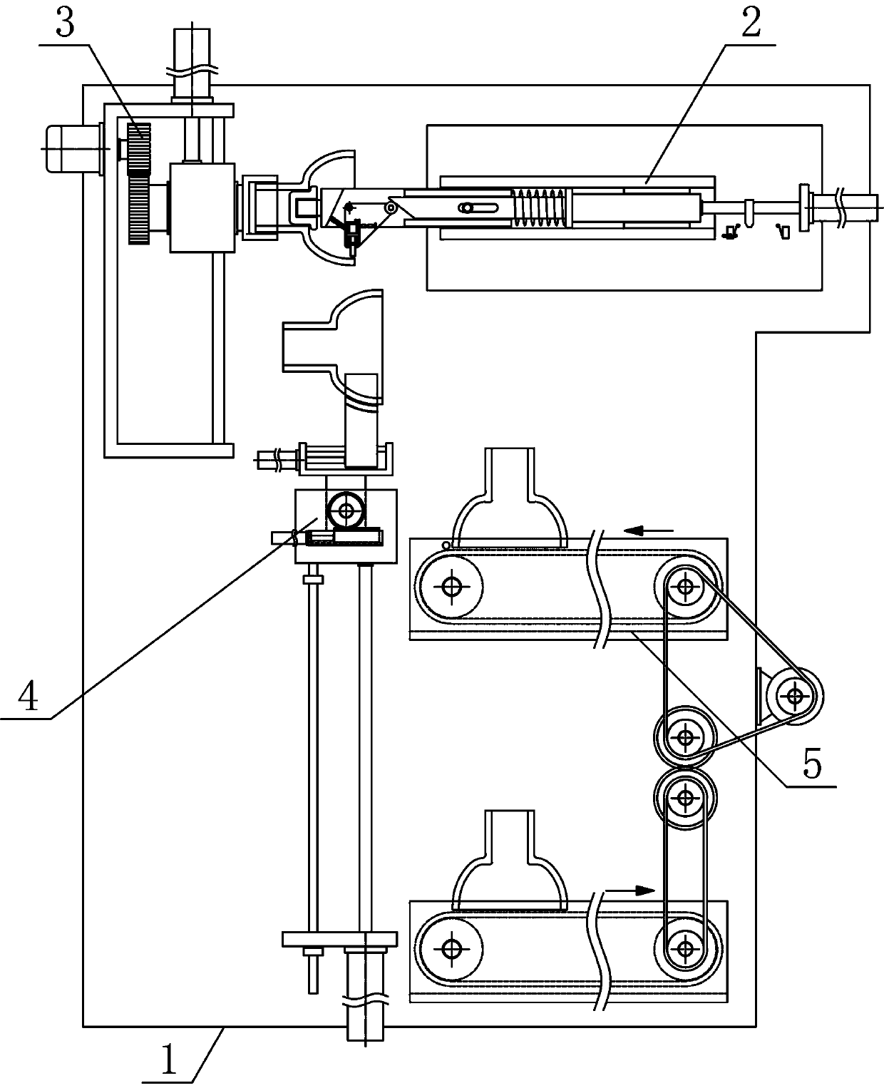
[0016] In order to further describe the present invention, a specific implementation of a spherical workpiece cutting and processing device will be further described below in conjunction with the accompanying drawings. The following examples are explanations of the present invention and the present invention is not limited to the following examples.

[0017] Such as figure 1 As shown, a spherical workpiece cutting and processing device of the present invention includes a processing material transfer support 1, a translation cutting mechanism 2, a material jam lifting mechanism 3, a turning material transfer mechanism 4 and a workpiece transmission mechanism 5, and the translation cutting mechanism 2 is fixed horizontally on the On the upper side of the processing material transfer support 1, the material jam lifting mechanism 3 is vertically arranged on the processing material delivery bracket 1 on the side of the translation cutting mechanism 2, and the turning material transf...


PUM


Abstract

The invention discloses a using method of a spherical workpiece cutting machining device, and belongs to the field of workpiece machining mechanical equipment. The spherical workpiece cutting machining device comprises a machining material conveying support, a translation cutting mechanism, a material clamping lifting mechanism, a turnover material transferring mechanism and a workpiece conveyingmechanism; the translation cutting mechanism is horizontally and fixedly arranged on one side above the machining material conveying support, the material clamping lifting mechanism is vertically arranged on the machining material conveying support on one side of the translation cutting mechanism, the turnover material transferring mechanism is vertically arranged on the machining material conveying support on one side below the material clamping lifting mechanism, and the workpiece conveying mechanism is horizontally and adjacently arranged on the machining material conveying support on one side of the turnover material transferring mechanism. The spherical workpiece cutting machining device is reasonable in structural design, capable of efficiently and stably cutting spherical workpiecesone by one, capable of achieving automatic transferring, feeding and returning of the spherical workpieces, high in machining automation degree and capable of meeting the requirements for workpiece machining and use.

Description

technical field [0001] The invention belongs to the field of workpiece processing machinery and equipment, and in particular relates to a method for using a spherical workpiece cutting and processing device, which is mainly applied to the continuous production and processing of spherical workpieces. Background technique [0002] Mechanical workpieces are single parts that make up machinery and machines that cannot be separated. It plays an important role in the automation industry. Mechanical workpieces include the connection of parts, supporting parts, lubricating lubrication systems and sealing parts. Components, parts of transmission systems that transmit motion and energy, shaft-type workpieces are the main type of workpieces, shaft-type workpieces are suitable for one or more CNC machine tools, shaft-type workpieces are one of the typical workpieces often encountered in hardware accessories 1. It is mainly used to support transmission parts, transmit torque and bear loa...

Claims


Application Information

Patent Timeline
Patent Type & Authority Applications(China)
IPC IPC(8): B23D79/00B23Q3/154B23Q5/22B23Q7/00B23Q7/03B23Q7/05B23Q7/06B23Q7/14B23Q15/22B23Q3/06
CPCB23D79/00B23Q3/06B23Q3/1543B23Q5/22B23Q7/00B23Q7/005B23Q7/03B23Q7/05B23Q7/06B23Q7/14B23Q15/22
Inventor 黄明珠
Owner 黄明珠
Why Eureka
Try Eureka