Automatic conveying device of metal round pipes

A transmission device and round tube technology, applied in the direction of conveyors, conveyor objects, transportation and packaging, etc., can solve the problems of easy equipment failure, offset rotation of metal round tubes, low degree of automation of metal round tube guide transmission, etc. , to achieve the effect of reasonable structural design and improved automation

Active Publication Date: 2020-08-14
肇庆智达自动化设备有限公司
View PDF8 Cites 2 Cited by
  • Summary
  • Abstract
  • Description
  • Claims
  • Application Information

AI Technical Summary

Problems solved by technology

During the production and processing of metal round tubes, the metal round tubes produced and processed by the previous process need to be conveyed and guided one by one to enable the processing of the subsequent process. The existing metal round tube transfer device has a complex structure and troublesome operation. It is difficult to realize the smooth and sequential delivery of the metal round tubes one by one. In the process of material guide transfer of the existing metal round tubes, it is difficult to use the gravity of the metal round tubes to automatically drop the metal round tubes one by one. Material transmission, metal tube material guide transmission mainly adopts mechanical retrieving device to pick up and place the metal tube, mechanical reclaiming device is mainly driven by drive motor and hydraulic cylinder, resulting in relatively high energy consumption for metal tube material transfer High, and the equipment is prone to failure, and the maintenance cost is high, so that the continuous high-frequency feeding and transfer of the metal round tube cannot be carried out. Accor...

Method used


Image

  • Automatic conveying device of metal round pipes
  • Automatic conveying device of metal round pipes
  • Automatic conveying device of metal round pipes

Examples


Embodiment Construction

[0026] In order to further describe the present invention, the specific implementation of a metal circular tube automatic conveying device will be further described below in conjunction with the accompanying drawings. The following examples are explanations of the present invention and the present invention is not limited to the following examples.

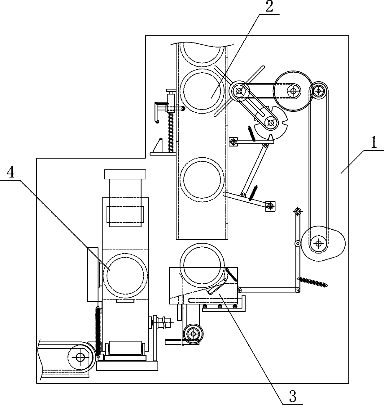
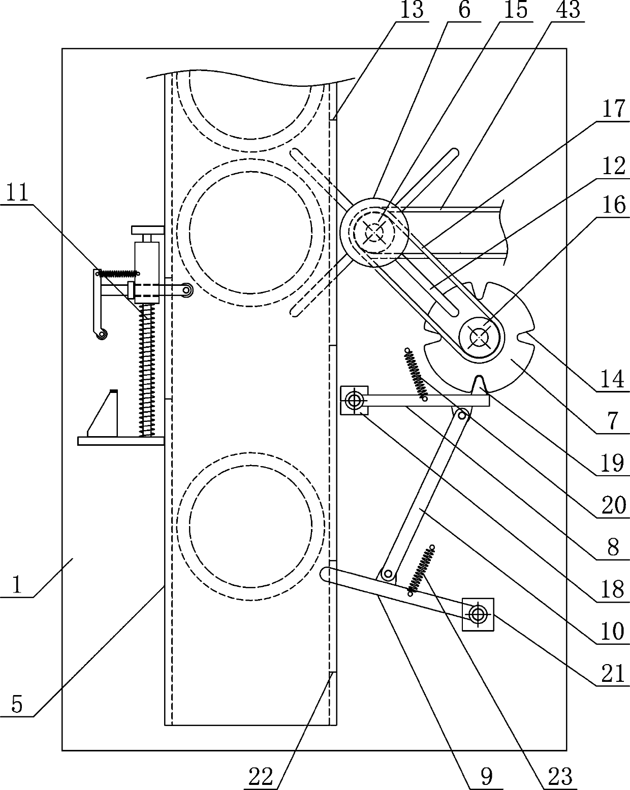
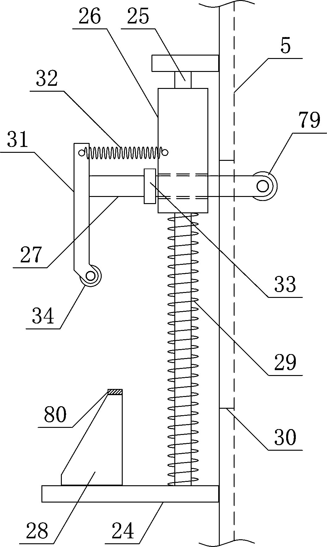
[0027] Such as figure 1 As shown, a metal round pipe automatic conveying device of the present invention includes a round pipe conveying bracket 1, a round pipe blanking mechanism 2, a round pipe transfer mechanism 3 and a round pipe turning mechanism 4, a round pipe blanking mechanism 2 and a round pipe transfer mechanism The mechanism 3 is vertically arranged on the round pipe transfer support 1 from top to bottom, and the round pipe turning mechanism 4 is vertically arranged on the round pipe transfer support 1 on one side of the round pipe transfer mechanism 3, such as figure 2 and image 3 As shown, the circular tube blanki...


PUM


Abstract

The invention discloses an automatic conveying device of metal round pipes and belongs to the field of pipe fitting conveying mechanical equipment. A round pipe falling mechanism and a round pipe transferring mechanism are sequentially arranged on a round pipe conveying support from top to bottom. A round pipe overturning mechanism is arranged at the position, on one side of the round pipe transferring mechanism, of the round pipe conveying support. A pipe bearing falling mechanism and a falling rotating disc are arranged on the two sides of a round pipe falling guide pipe correspondingly. A round pipe transferring bearing plate is arranged on a horizontal moving limiting support in a sliding manner. A reciprocating rotating round plate is arranged on a guide plate rotating support. A round pipe overturning containing chamber of a square structure is arranged on the outer side of the reciprocating rotating round plate. A round pipe conveying belt is arranged at the position, on one side of the lower end of the reciprocating rotating round plate, of the round pipe conveying support. The automatic conveying device is reasonable in structural design, the metal round pipes can be stably and efficiently guided and conveyed one by one smoothly and continuously, the metal round pipes can be automatically and accurately overturned to adjust the stations, the automatic degree of metal round pipe conveying is increased, and the machining use requirement is met.

Description

technical field [0001] The invention belongs to the field of mechanical equipment for conveying pipe fittings, and in particular relates to an automatic conveying device for metal round pipes, which is mainly used for continuous conveying and processing of metal round pipes. Background technique [0002] Metal round pipe refers to a cylindrical structural pipe made of metal materials with openings at both ends and a hollow concentric section. It can be used in the fields of pipelines, thermal equipment, machinery industry and chemical industry. Different types can be divided into seamless round tubes and welded round tubes. In addition to classifying metal round tubes according to processing technology, metal round tubes can also be classified according to usage, connection methods and materials. There are many types of metal round pipes. Metal round pipes used in different fields need to use metal materials of different materials. The quality of metal materials directly det...

Claims


Application Information

Patent Timeline
IPC IPC(8): B65G47/74B65G47/248
CPCB65G47/088B65G47/248B65G2201/0276
Inventor 於金亚
Owner 肇庆智达自动化设备有限公司
Why Eureka
Try Eureka