Vibrating screen intelligent cleaning system

An intelligent cleaning system and vibrating screen technology, applied in the direction of mobile filter element filter, separation method, filtration separation, etc., can solve the problems of manual operation, time-consuming and laborious environmental pollution, etc., and achieve simple installation, reduce water consumption, and ensure cleaning effect. Effect

Active Publication Date: 2021-11-05
西安海域环保科技有限公司
View PDF5 Cites 0 Cited by
  • Summary
  • Abstract
  • Description
  • Claims
  • Application Information

AI Technical Summary

Problems solved by technology

In view of the above situation, the screen mud should be treated in a timely and effective manner, but manual operation is time-consuming and labor-intensive, and it is easy to produce new environmental pollution

Method used


Image

  • Vibrating screen intelligent cleaning system
  • Vibrating screen intelligent cleaning system
  • Vibrating screen intelligent cleaning system

Examples


specific Embodiment approach 1

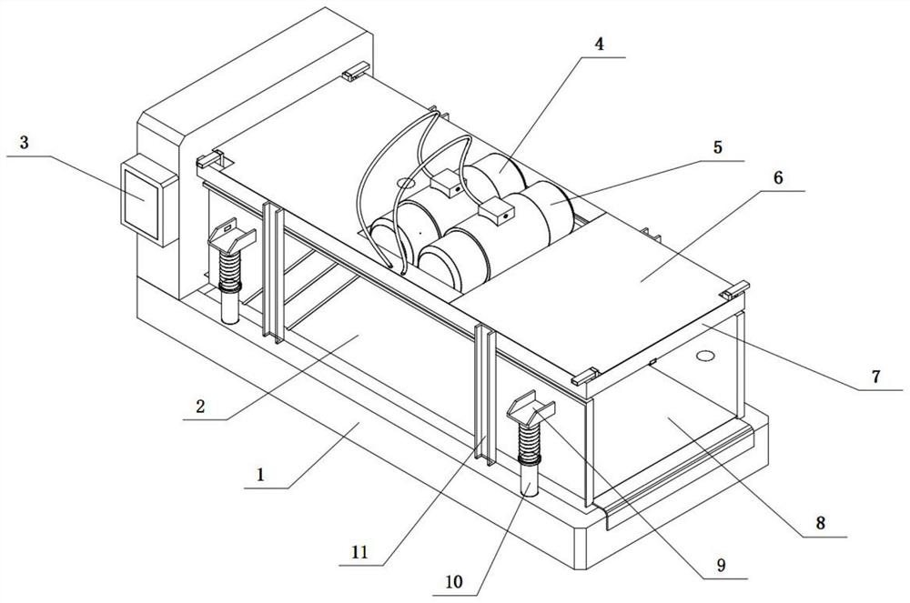
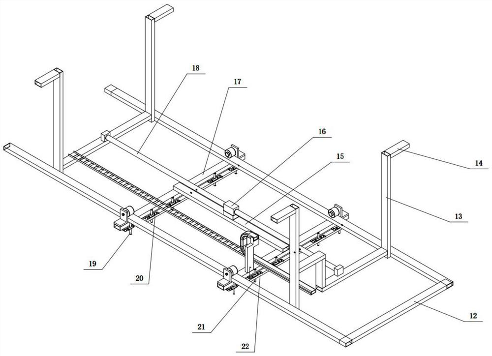
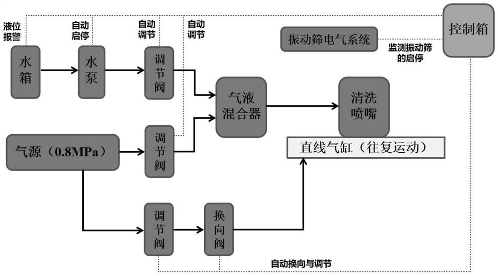
[0021] Combine below Figure 1-3 This embodiment is described. The present invention relates to the field of vibrating screen treatment, more specifically, an intelligent cleaning system for vibrating screens, including a base 1, a screen box 2, a rectangular top frame 7, a screen 8, a convex seat 9, a vertical sleeve 10, Support rod 11, rectangular bottom frame 12, door-shaped support beam 13, hook 14, nozzle I19, air pipe 20, nozzle II21 and liquid pipe 22, the present invention adopts the gas-liquid two-phase cleaning method to ensure the cleaning effect and greatly reduce the water consumption , does not affect the performance of drilling fluid.

[0022] The front and rear sides of the rectangular top frame 7 are fixedly connected with two support rods 11, and the four support rods 11 are fixedly connected on the upper side of the base 1, and the bottom of the screen box 2 is provided with a screen 8, and the bottom of the screen box 2 The upper side, left side and right ...

specific Embodiment approach 2

[0026] Combine below Figure 1-3 To illustrate this embodiment, the vibrating screen intelligent cleaning system further includes a top cover 6 , and the top covers 6 are provided on the left and right sides of the base 1 .

specific Embodiment approach 3

[0027] Combine below Figure 1-3 To illustrate this embodiment, the vibrating screen intelligent cleaning system also includes a control box 3, an air pump 4 and a water pump 5, the left part of the base 1 is provided with a control box 3, and the middle part of the rectangular top frame 7 is fixedly connected with an air pump 4 and a water pump 5, The air pump 4 is connected to the air pipe 20 through a flexible pipe, and the water pump 5 is connected to the liquid pipe 22 through a flexible pipe. The air pump 4 and the water pump 5 pass gas into the air pipe 20 and water into the liquid pipe 22 respectively.


PUM

PropertyMeasurementUnit
densityaaaaaaaaaa

Abstract

The invention relates to the field of vibrating screen treatment, more specifically, an intelligent cleaning system for vibrating screens, including a base, a screen box, a rectangular top frame, a screen mesh, a convex seat, a vertical sleeve column, a support rod, a rectangular bottom frame, and a door-shaped support beam , hook, nozzle I, gas pipe, nozzle II and liquid pipe, the present invention adopts the gas-liquid two-phase cleaning method to ensure the cleaning effect while greatly reducing the water consumption without affecting the performance of the drilling fluid. The front and rear sides of the rectangular top frame are fixedly connected with two support rods, and the four support rods are fixedly connected to the upper side of the base, the bottom of the screen box is provided with a screen, and the upper side, left side and right side of the screen box are The sides are all open structures, the screen box is set on the lower side of the rectangular top frame, the screen box is set on the upper side of the base, the front and rear sides of the screen box are fixedly connected with convex seats, and the four corners of the upper side of the base are fixedly connected There are vertical sleeve columns, the upper ends of the four vertical sleeve columns are all fixedly connected with springs, and the upper ends of the four springs are respectively fixedly connected with the four convex seats.

Description

technical field [0001] The invention relates to the field of vibrating sieve processing, in particular to an intelligent cleaning system for vibrating sieves. Background technique [0002] The drilling fluid shale shaker is the first-stage purification equipment of the solid control system, and its main function is to remove harmful solid particles in the drilling fluid. With the application of new drilling technologies and drilling tools, the requirements for the control level of drilling fluid solids are constantly increasing. Drilling mud contains a large amount of pollutants such as hydrocarbons, salts, organic polymers and heavy metals. The density of the mud is as high as 2.8g / cm3 and the viscosity is as high as 120s. The attachment of high-viscosity mud to the screen is not conducive to screen penetration. Pulping phenomenon". In view of the above situation, the screen mud should be treated in a timely and effective manner, but manual operation is time-consuming and...

Claims


Application Information

Patent Timeline
Patent Type & Authority Patents(China)
IPC IPC(8): B01D33/03B01D33/48
CPCB01D33/0346B01D33/48
Inventor 王洪彦陈璞刘朝曦李金龙李小鹏石宪锋陈宁生
Owner 西安海域环保科技有限公司
Why Eureka
Try Eureka