Light-emitting fan

A technology of a fan and a light-emitting unit, applied in the field of fans, can solve the problems of shortening the light transmission path, the light-emitting fan cannot produce a uniform brightness effect, and the diffusion angle is small.

Active Publication Date: 2020-08-25
PRIMAX ELECTRONICS LTD
View PDF8 Cites 1 Cited by
  • Summary
  • Abstract
  • Description
  • Claims
  • Application Information

AI Technical Summary

Problems solved by technology

[0004] However, because the light emitted by the solid-state light source is mostly linear, and its diffusion angle is small, when the volume of the light-emitting fan is reduced, the path of light transmission is likely to be shortened, resulting in an excessively concentrated range of light projection. This will not only make the light-emitting fan In addition to the decrease in the overall luminous intensity, too concentrated light will also form uneven brightness noise (hot spot) at the projected position, resulting in the inability of the luminous fan to produce a uniform brightness effect

Method used


Image

  • Light-emitting fan
  • Light-emitting fan
  • Light-emitting fan

Examples


Embodiment Construction

[0065] The advantages and features of the present invention and methods for attaining the same will be more easily understood by more detailed description with reference to exemplary embodiments and accompanying drawings. However, the invention may be embodied in different forms and should not be construed as limited to the embodiments set forth herein. On the contrary, for those skilled in the art, these embodiments are provided to make this disclosure more thorough, comprehensive and fully convey the scope of the present invention.

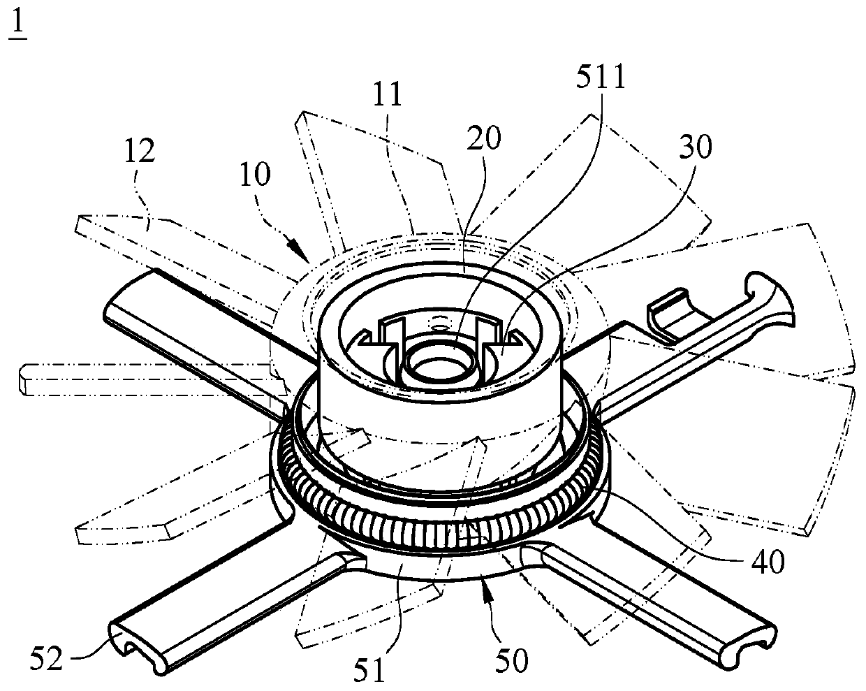
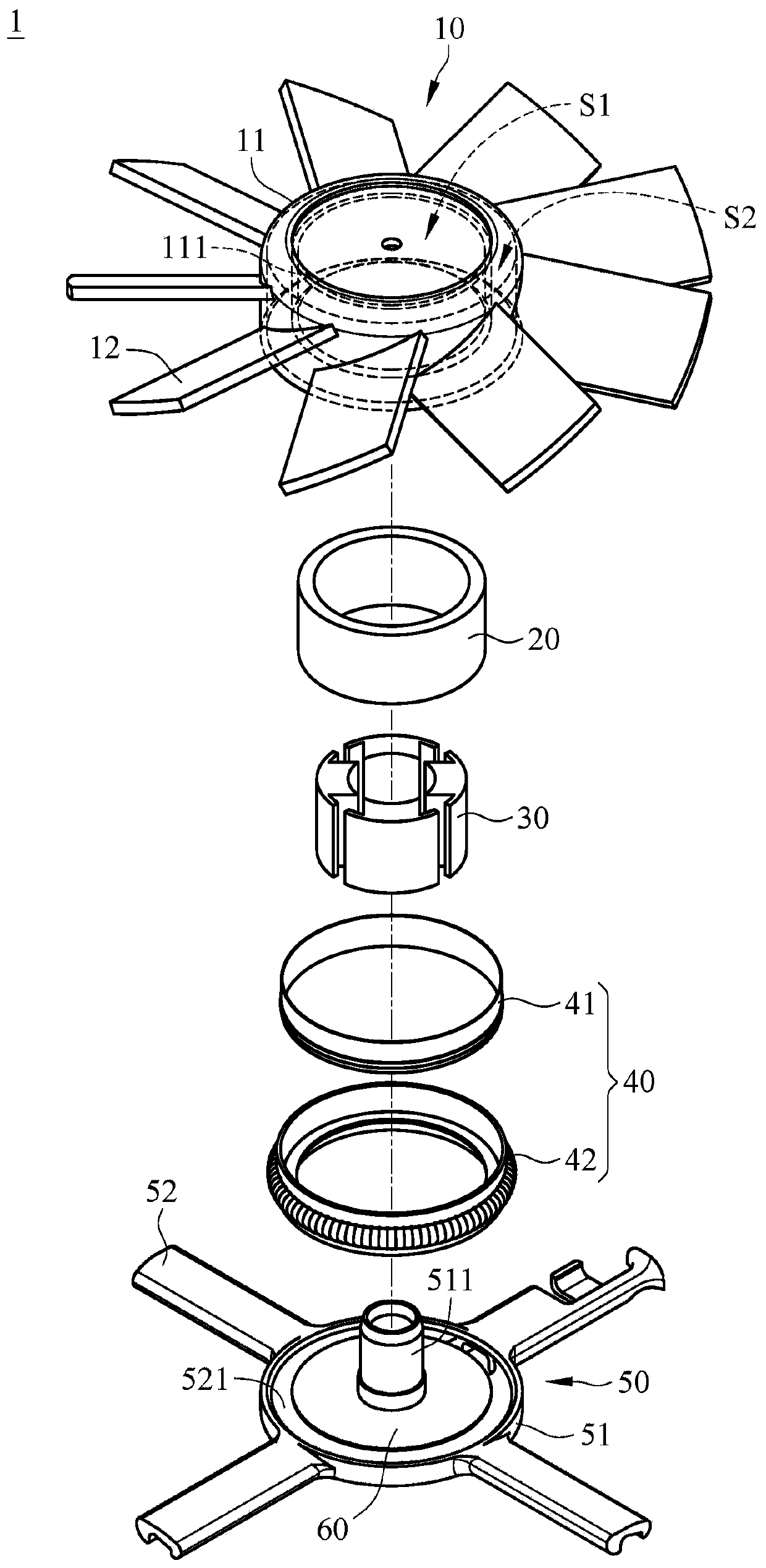
[0066] First, see Figure 1A and Figure 1B as shown, Figure 1A It is a three-dimensional schematic diagram of the luminous fan of the present invention; Figure 1B It is a three-dimensional exploded view of the luminous fan of the present invention. The light-emitting fan 1 includes: a light-guiding fan wheel 10 , a rotor set 20 , a stator set 30 , a light-emitting module 40 , a supporting structure 50 and a main circuit board 60 .

[0067]...


PUM


Abstract

The invention provides a light-emitting fan. The light-emitting fan comprises a supporting structure, a main circuit board, a light guide fan wheel and a light-emitting module; the light guide fan wheel is pivoted on a bracket of the supporting structure; and the light-emitting module is arranged in a hub of the light guide fan wheel, and a light-emitting unit of the light-emitting module emits light to the adjacent lens elements and transmits the light to the light guide fan wheel through refraction of secondary lens of the lens elements, so that the light guide fan wheel emits the light.

Description

technical field [0001] The invention relates to a fan, in particular to a fan with a light emitting function. Background technique [0002] In today's life, desktop computers have become necessary household appliances for small and medium-sized families, and general household computer hosts are equipped with cooling fans, which are used to exhaust the heat in the host casing to prevent processors, motherboards or hard disks from cooling. Damage caused by overheating. [0003] In order to meet the needs or preferences of different users, currently there are computer hosts with transparent shells on the market, so that users can directly observe the internal structure or status of the computer host. On the other hand, it may also be equipped with a cooling fan with a light-emitting function, so that when the main computer is turned on, the cooling fan with a light-emitting function can emit light and dissipate heat at the same time. The overall appearance of the host is more...

Claims


Application Information

Patent Timeline
Patent Type & Authority Applications(China)
IPC IPC(8): F04D19/00F04D29/32F21V33/00
CPCF04D19/002F04D29/325F04D29/329F21V33/0052
Inventor 黄韦强詹伟平
Owner PRIMAX ELECTRONICS LTD
Why Eureka
Try Eureka