Optical head devcie with single object lens

A technology of optical head device and objective lens, which is applied in the direction of optical recording head, light beam guiding device, optics, etc., and can solve the problems of complicated structure and increased manufacturing cost

Inactive Publication Date: 2004-04-21
SAMSUNG ELECTRONICS CO LTD
View PDF5 Cites 0 Cited by
  • Summary
  • Abstract
  • Description
  • Claims
  • Application Information

AI Technical Summary

Problems solved by technology

In this case, since a driving device is required to replace the lens, ...

Method used


Image

  • Optical head devcie with single object lens
  • Optical head devcie with single object lens
  • Optical head devcie with single object lens

Examples


Embodiment Construction

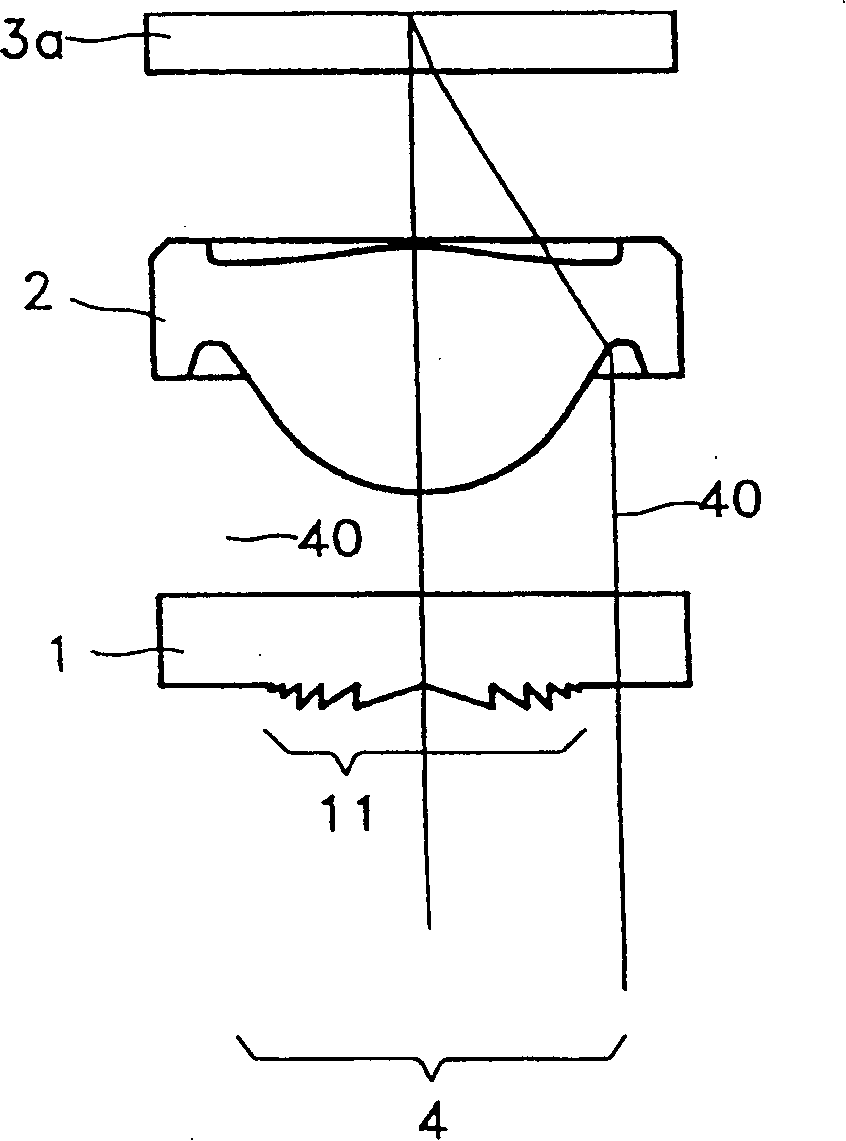
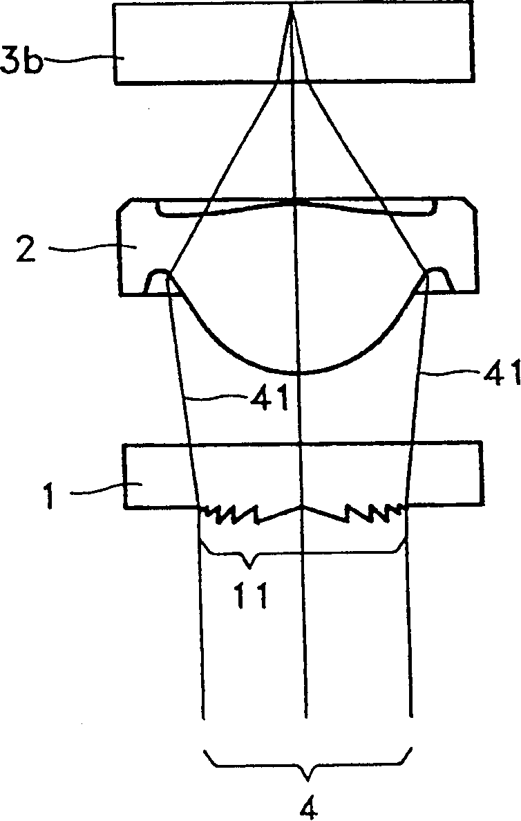
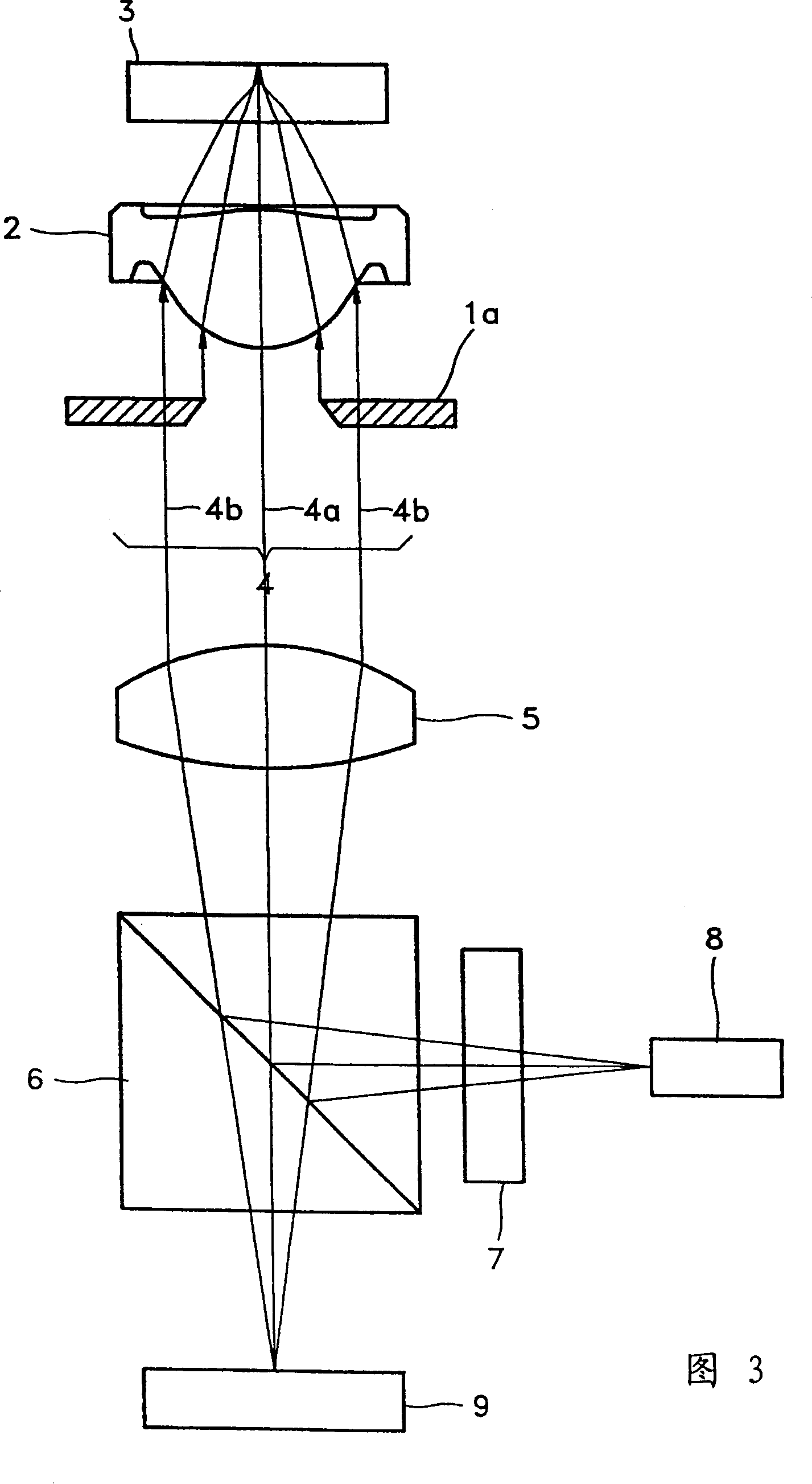
[0048] In the present invention, the light located in the intermediate region around the central axis of the light transmission channel is blocked or shielded. The intermediate zone is located between a zone close to the axis ("adaxial zone") and a zone further away from the axis ("abaxial zone"). Blocking light in the intermediate zone causes light from both the paraxial and distal zones to form a small spot, while at the same time making the side lobes around the spot in the focal zone of the lens smaller by suppressing interference from other light present in the intermediate zone. minimum.

[0049] Here, the paraxial region refers to a region around the lens axis (ie, the optical axis), having negligible aberration, and focusing near the paraxial focal point. The abaxial region refers to a region that is farther from the optical axis than the paraxial region and can form a focal region near the peripheral focus. The intermediate zone refers to the area between the adaxia...


PUM


Abstract

An optical pickup device for reproducing and recording the optical disc information having different thicknesses includes an objective lens which focuses the light from the light source on the optical discs focusing section. The objective lens contains a paraxial region, an abaxial region, and a middle abaxial region locating between the paraxial region and the abaxial region and controlling the light incident to the region, and the said objective lens has different focuses on the same optical axis according to the different thickness. When the thin discs are used, the spot focused on theoptical discs focusing section contains the incident light from said paraxial region and abaxial region; when the thick discs are used, the spot focused on theoptical discs focusing section contains the incident light from said paraxial region.

Description

[0001] This application is a divisional application of an invention patent application filed on August 28, 1996 by Samsung Electronics Co., Ltd. with the title of "lens device and optical head device using the lens device" and application number 96191002.X. technical field [0002] The invention relates to an optical head device using a single objective lens. Background technique [0003] The optical head records and reproduces information such as video or audio on a recording medium such as an optical disc. An optical disc is constituted by forming an information recording surface on a substrate. The substrate can be made of plastic or glass. In order to read or write information from a high-density optical disc, the spot diameter must be very small. For this reason, objective lenses with large numerical apertures and light sources with shorter wavelengths are usually used. However, when using a light source with a shorter wavelength, it is necessary to reduce the tilt t...

Claims


Application Information

Patent Timeline
IPC IPC(8): G02B3/00B29D11/00G02B3/10G02B7/28G02B13/00G02B27/09G02B27/58G11B7/00G11B7/004G11B7/0045G11B7/005G11B7/085G11B7/09G11B7/125G11B7/13G11B7/135G11B7/1381
CPCB29D11/00009G11B7/1367G11B7/139G11B7/0045G11B7/1374G02B27/58G11B7/1381G02B3/10G11B7/133G11B7/005G11B7/0909G11B2007/13727G11B2007/0006G11B7/13922G11B7/1353
Inventor 李哲雨申东镐林庆和郑钟三赵虔皓成平庸刘长勋李庸勋
Owner SAMSUNG ELECTRONICS CO LTD
Why Eureka
Try Eureka