Illuminating device and projection display device using the same

Inactive Publication Date: 2012-06-21
NEC DISPLAY SOLUTIONS LTD
View PDF5 Cites 0 Cited by
  • Summary
  • Abstract
  • Description
  • Claims
  • Application Information

AI Technical Summary

Benefits of technology

[0024]It is an object of the present invention to provide a compact illuminating device capable of increasing light use efficiency by imp

Problems solved by technology

Thus, a light loss occurs on the surface of the LED, thus preventing realization of high polarizing conversion efficiency.
The illuminating device described in Patent Literature 3 is difficult to be miniaturized because of the use of the PBS polarizing conversion arra

Method used


Image

  • Illuminating device and projection display device using the same
  • Illuminating device and projection display device using the same
  • Illuminating device and projection display device using the same

Examples


first exemplary embodiment

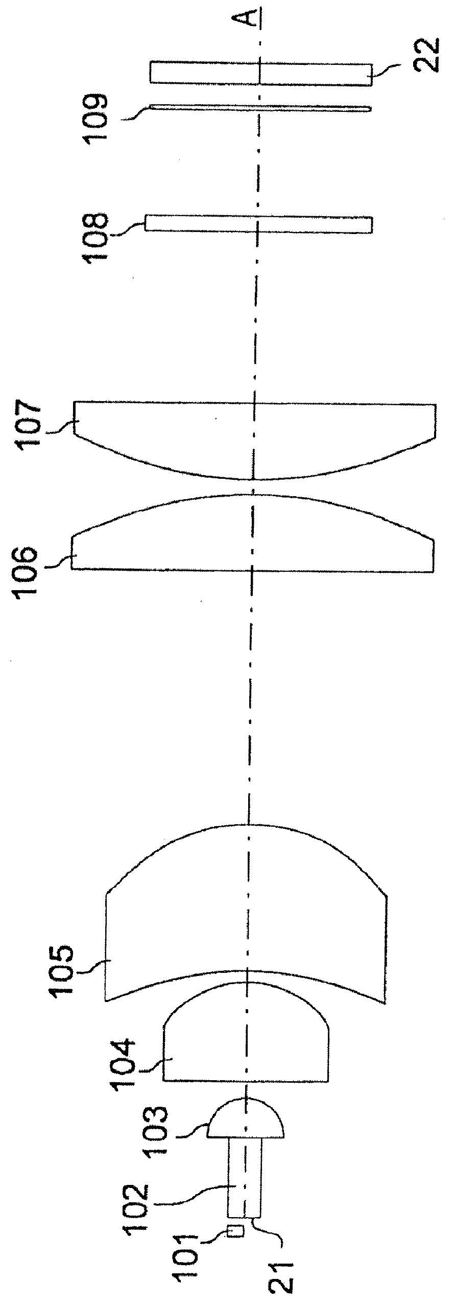
[0067]FIG. 1 is a schematic view showing a configuration of an illuminating device according to a first exemplary embodiment of the present invention.

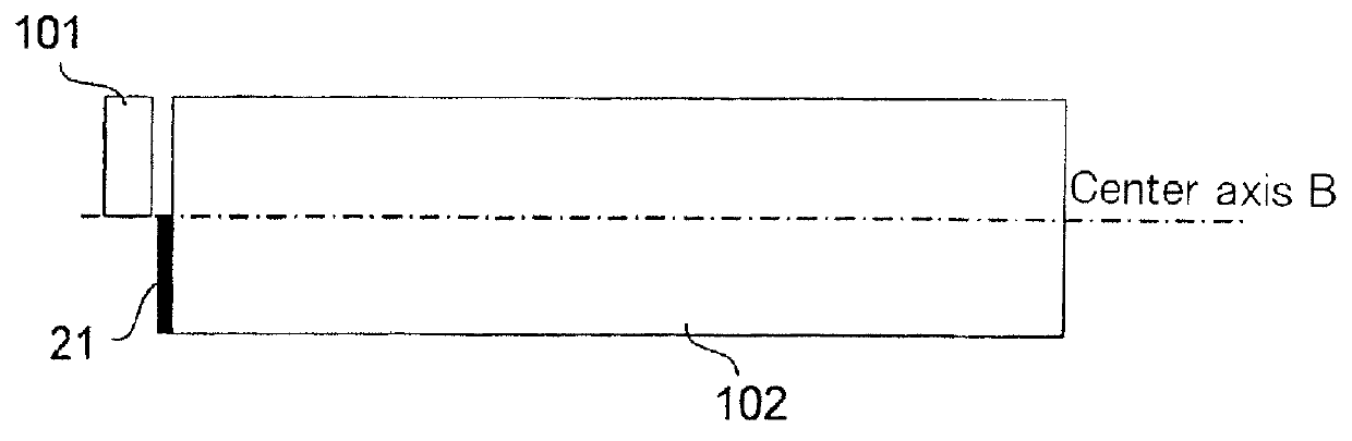
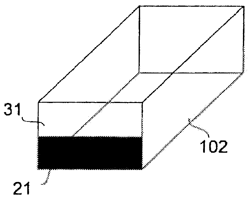
[0068]As shown in FIG. 1, the illuminating device according to the present embodiment, which illuminates display element 22 having reflective polarizing plate 109, includes, in addition to reflective polarizing plate 109, light source 101, light guiding rod 102, illumination lenses 103 to 107, and phase plate 108.

[0069]Reflective polarizing plate 109 is, for example, a polarizing plate of a wire-grid type, and configured to transmit, among incident lights, first polarized light (e.g., p-polarized light) while reflecting second polarized light (e.g., s-polarized light) whose polarized state is different from the first polarized light in a direction (toward light guiding plate 102) opposite the incident direction.

[0070]Display element 22 includes, for example, a liquid crystal panel. For both reflective polarizing plate 109 and display e...

second exemplary embodiment

[0124]An illuminating device according to the present exemplary embodiment is configured so that lights from a plurality of light sources having peak wavelengths in different wavelength bands enter a light guiding rod. This point is different from the illuminating device according to the first exemplary embodiment. Other components are similar to those of the illuminating device according to the first exemplary embodiment.

[0125]FIG. 9 is a schematic view showing a feature portion of an illuminating device according to the second exemplary embodiment of the present invention. Referring to FIG. 9, the illuminating device includes light sources 96G and 97G having peak wavelengths in a green wavelength band, light source 98R having a peak wavelength in a red wavelength band, and light source 99B having a peak wavelength in a blue wavelength band. These light sources are solid light sources (e.g., LEDs).

[0126]Light from light source 96G enters one end surface (incident surface) of light ...


PUM


Abstract

An illuminating device includes: light source (101); light guiding means (102) where light from light (101) is supplied to one end surface, and light incident from the one end surface is propagated inside to exit from the other end surface; illuminating optical systems (103 to 107) that form an optical image formed on the other end surface of light guiding means (102) on display element (22); reflective polarizing plate (109) that is located between illuminating optical systems (103 to 107) and display element (12), and transmits first polarized light while reflecting second polarized light whose polarized state is different from the first polarized light toward illuminating optical systems (103 to 107); phase plate (108) located between light guiding means (102) and reflective polarizing plate (109); and reflecting means (21) that is located on a side opposite the one end surface of light guiding means (102), and reflects, among lights by reflective polarizing plate (109), light incident via phase plate (108), illuminating optical systems (103 to 107), and light guiding means (102) toward the one end surface of light guiding means (102). The light emitting center of light source (101) is shifted from a center axis of light guiding means (102).

Description

TECHNICAL FIELD [0001]The present invention relates to an illuminating device of a projection display device represented by a liquid crystal projector, and more particularly to an illuminating device that illuminates a display element including a conversion element.BACKGROUND ART[0002]Patent Literatures 1 and 2 discuss a projector that uses a LED (Light Emitting Diode) as a light source for illuminating a DMD (Digital Micromirror Device) serving as a display element (Patent Literatures 1 and 2). The projector of this type is expected to reduce costs more than a projector that uses a white discharge lamp, and achieve performance including miniaturization, lower power consumption, and a wider color reproduction range.[0003]There are also a projector that uses a single LCoS (Liquid Crystal on Silicon) element (Nonpatent Literature 1), and a projector that users three liquid crystal panels as display elements (Nonpatent Literatures 2 and 3).[0004]In the liquid crystal projector, usually...

Claims


Application Information

Patent Timeline
IPC IPC(8): G03B21/14F21V9/14
CPCG03B21/14H04N9/3167H04N9/3152G03B21/2013G03B21/2033G03B21/2066G03B21/208
Inventor KATOU, ATSUSHI
Owner NEC DISPLAY SOLUTIONS LTD
Why Eureka
Try Eureka