Light guide panel and backlight module

A technology of backlight module and light guide plate, applied in the direction of light guide, optics, optical components, etc., can solve the problem of insufficient light output capability of the backlight module 100, and achieve the effect of good light use efficiency, high uniformity, and improved light use efficiency.

Inactive Publication Date: 2013-08-28
CORETRONIC
View PDF13 Cites 1 Cited by
  • Summary
  • Abstract
  • Description
  • Claims
  • Application Information

AI Technical Summary

Problems solved by technology

Therefore, in the existing backlight module 100, the light beam transmitted to the outside of the light-transmitting substrate 122 through the surface S1 will be reduced, resulting in insufficient overall light output capability of the backlight module 100.

Method used


Image

  • Light guide panel and backlight module
  • Light guide panel and backlight module
  • Light guide panel and backlight module

Examples


no. 1 example

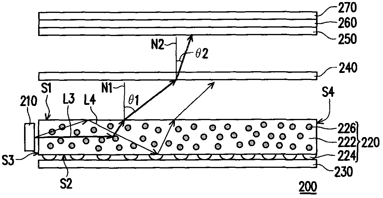
[0050] figure 2 It is a schematic diagram of the backlight module according to the first embodiment of the present invention. Please refer to figure 2 , the backlight module 200 of this embodiment includes a light emitting element 210 and a light guide plate 220 . The light emitting element 210 is used to emit a light beam L3. The light guide plate 220 is disposed beside the light emitting element 210 and is used to guide the light beam L3. In this embodiment, the light emitting element 210 is, for example, a light emitting diode (light emitting diode, LED). The light guide plate 220 includes a transparent substrate 222 , a plurality of optical microstructures 224 and a plurality of diffusion particles 226 .

[0051]The transparent substrate 222 has a surface S1, a surface S2 opposite to the surface S1, a light incident surface S3 connecting the surface S1 and the surface S2, and a surface S4 opposite to the light incident surface S3, wherein the light beam L3 enters thr...

no. 2 example

[0066] Figure 4 It is a schematic diagram of the backlight module according to the second embodiment of the present invention. like Figure 4 As shown, the backlight module 300 with figure 2 The backlight module 200 is similar to the above-mentioned backlight module 200, the main difference between the two is: the optical microstructure 224 of the backlight module 300 is configured on the surface S1. Since the backlight module 300 of this embodiment can be composed of Figure 2 ~ Figure 3B There are sufficient teachings, suggestions and implementation descriptions obtained in the description of the embodiments, so the details are not repeated here.

no. 3 example

[0068] Figure 5 It is a schematic diagram of the backlight module according to the third embodiment of the present invention. like Figure 5 As shown, the backlight module 400 with figure 2 The backlight module 200 is similar to the backlight module 200, but the main difference is that the backlight module 400 also includes a light-emitting element 280, and the light-transmitting substrate 222' also has a light incident surface S4' opposite to the light incident surface S3, wherein The light emitting element 280 is disposed beside the light incident surface S4'.

[0069] like Figure 5 As shown, the light-emitting element 280 is used to emit the light beam L5, and since the diffusion particles 226 are added inside the light-transmitting substrate 222 ′, the light beam L5 will change its trajectory due to collision with the diffusion particles 226 , and then directly pass through the surface S1 to the light-transmitting substrate 222 ′. outside the substrate 222'. In thi...


PUM

PropertyMeasurementUnit
hazeaaaaaaaaaa
hazeaaaaaaaaaa
hazeaaaaaaaaaa

Abstract

The invention provides a light guide panel and a backlight module. The light guide panel is suitable for guiding a light emitting element to emit a light beam. The light guide panel comprises a non-lighttight base plate, a plurality of optical microstructures and a plurality of diffusion particles, wherein the non-lighttight base plate is provided with a first surface, a second surface and a light incident plane; the second surface is opposite the first surface; the light incident plane is connected with the first surface and the second surface; the light beam is suitable for entering the non-lighttight base plate via the light incident plane; the optical microstructures are arranged on the second surface; the diffusion particles are distributed in the non-lighttight base plate; and the haze degree of the light guide panel is greater than or equal to 0.4% and less than or equal to 80%. The invention also provides a backlight module using the light guide panel.

Description

【Technical field】 [0001] The present invention relates to an optical element and a light source module, and in particular to a light guide plate and a backlight module. 【Background technique】 [0002] The backlight module usually includes a light guide plate, and the function of the light guide plate is to guide the scattering direction of the light beam generated by the light source, to improve the luminance of the panel, and to ensure the uniformity of the panel brightness, so that the point light source or line in the backlight module The light source is converted into a surface light source and supplied to the liquid crystal display panel. In detail, when the light beam enters the light guide plate, since the light guide plate body is transparent and clear, it will not cause deflection and scattering of the light beam, so the light beam will be transmitted to the outside of the light guide plate or through the microscopic surface of the light guide plate in the way of to...

Claims


Application Information

Patent Timeline
Patent Type & Authority Patents(China)
IPC IPC(8): G02F1/1335G02B6/00F21V8/00
Inventor 萧增科刘振坤
Owner CORETRONIC
Why Eureka
Try Eureka