High-power LED lamp heat dissipation device

A technology of LED lamps and heat sinks, which is applied to the cooling/heating devices of lighting devices, lighting devices, components of lighting devices, etc., can solve the problem that the heat exchange performance needs to be further improved, the work adaptability is poor, and the reflux of condensing working fluid is blocked. and other problems, to achieve excellent work adaptability, improve the drying limit, improve the temperature uniformity and heat transfer limit.

Active Publication Date: 2020-09-29
YANGZHOU UNIV +1
View PDF12 Cites 1 Cited by
  • Summary
  • Abstract
  • Description
  • Claims
  • Application Information

AI Technical Summary

Problems solved by technology

Therefore, when this type of heat pipe works in the reverse gravity mode (that is, the evaporating section (hot end) is at the upper relative working position, and the condensing section (cold end) is at the lower relative working position), there will be a problem that the reflux of the condensing working medium is blocked, and the heat transfer efficiency It will be greatly reduced or even fail, so that the related heat pipe type LED cooling and heat dissipation device still has technical bottlenecks such as poor work adaptability and inability to work in the direction of gravity, which greatly limits its scope of use.
Furthermore, due to the limitation of the thermal conductivity of the solid metal, the heat transfer performance of the extended heat dissipation surface of the metal fins matched with the heat pipe still needs to be further improved

Method used


Image

  • High-power LED lamp heat dissipation device
  • High-power LED lamp heat dissipation device
  • High-power LED lamp heat dissipation device

Examples


Embodiment Construction

[0023] The present invention will be further described below in conjunction with accompanying drawing:

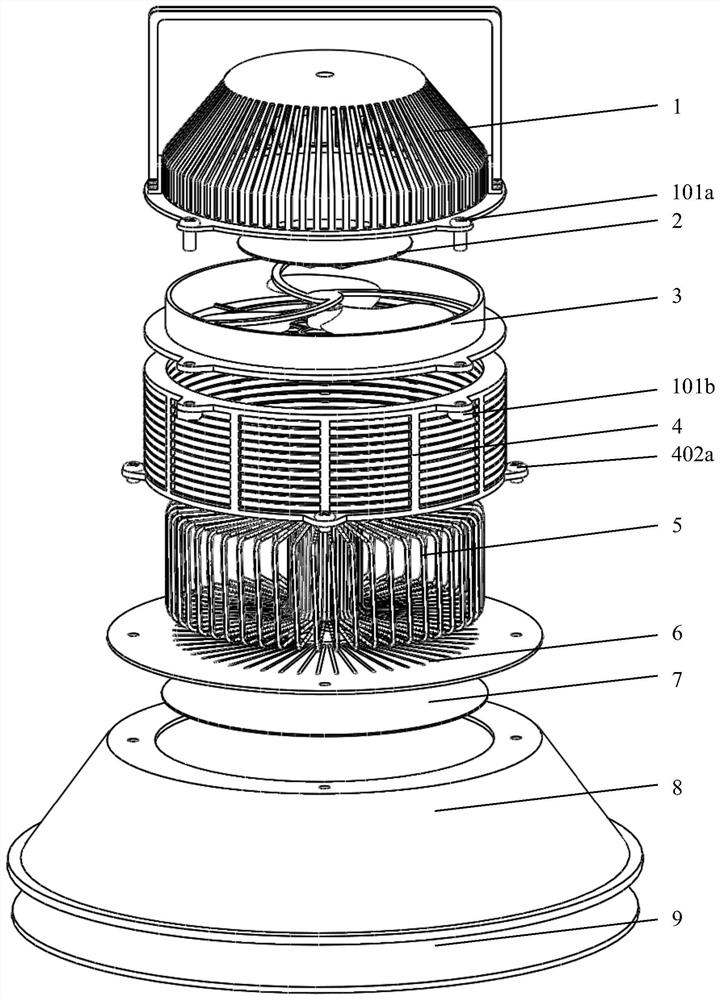
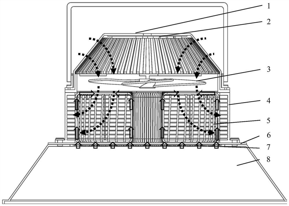
[0024] Such as Figure 1-2 As shown, a high-power LED lamp cooling device consists of an upper lampshade 1, a circuit board 2, a cooling fan 3, a finned shell 4, a gas-liquid pulsation phase change heat pipe 5, a mounting base 6, and an LED bead integrated board 7 , lower lampshade 8, and glass cover plate 9 parts are assembled. The gas-liquid pulsation phase change heat pipe 5 is vertically and closely installed on the installation surface of the preset installation groove 602 of the installation base 6, and the contact pipe section forms an endothermic evaporation section, and the remaining pipe sections are heat release condensation sections; the other side of the installation base 6 The LED lamp bead integrated board 7 is then coaxially bonded; each contact surface is connected with a high-temperature-resistant heat-conducting adhesive. The finned housing 4 is used as...


PUM


Abstract

The invention relates to a high-power LED lamp heat dissipation device, and belongs to the technical field of LED heat dissipation. The high-power LED lamp heat dissipation device comprises an upper lampshade, a circuit board, a heat dissipation fan, a ribbed shell, a gas-liquid pulsating phase change heat pipe, a mounting base, an LED lamp bead integrated board, a lower lampshade and a glass cover plate. The high-power LED lamp heat dissipation device takes the gas-liquid pulsating phase change heat pipe as a core heat transfer component, and heat production of a bottom high-power LED lamp bead array is efficiently transmitted to a three-dimensional space and dissipated quickly; a self-wetting fluid working medium filled in the pipe can automatically moisten the evaporation section of theheat pipe, and the "drying" limit of the heat pipe can be effectively improved; and the capillary suction produced by micro grooves on the inner wall of the heat pipe can further enhance the wettability of the working medium to the inner wall of a whole pipe body, so that the temperature uniformity and heat transfer limit are further improved. Compared with an existing metal ribbed LED lighting and heat dissipation device and traditional heat pipe LED lighting and heat dissipation devices such as capillary heat pipes and gravity heat pipes, the high-power LED lamp heat dissipation device hasbetter heat transfer performance, higher heat transfer limit and better working adaptability.

Description

technical field [0001] The invention belongs to the technical field of LED heat dissipation, and relates to an LED lamp heat dissipation device, in particular to a high-power LED heat dissipation device. Background technique [0002] LED (Light Emitting Diode, Light Emitting Diode) is a high-efficiency electro-optical conversion semiconductor device, which is widely used in various lighting scenarios. Because the luminous flux of a single LED lamp is low, practical high-power LED lamps (such as projection lamps, wall washers, etc.) are usually integrated with a large number of arrayed LED lamp beads to make the luminous flux meet the actual application requirements. It is worth noting that although the electro-optical conversion efficiency of LED is relatively high, most of the electric energy will still be converted into heat energy. If it is not effectively dissipated and cooled, the operating temperature of the LED chip will exceed its safe operating temperature limit (ab...

Claims


Application Information

Patent Timeline
Patent Type & Authority Applications(China)
IPC IPC(8): F21V29/67F21V29/89F21V29/51F21V29/58F21V29/70F21V17/12F21Y115/10
CPCF21V29/67F21V29/89F21V29/51F21V29/58F21V29/70F21V17/12F21Y2115/10
Inventor 刘向东韩笑天陈永平徐德好
Owner YANGZHOU UNIV
Why Eureka
Try Eureka