Power distribution cooperation system based on intelligent charging energy router and cooperation method thereof

A technology of intelligent charging and collaborative system, applied in power network operating system integration, information technology support system, AC network voltage adjustment, etc. Problems such as the ineffective utilization of resources and power in the distribution network

Active Publication Date: 2020-10-23
SHENZHEN DINGWANG TECH CO LTD
View PDF5 Cites 2 Cited by
  • Summary
  • Abstract
  • Description
  • Claims
  • Application Information

AI Technical Summary

Problems solved by technology

[0004] The main purpose of the present invention is to provide a power distribution coordination system and method based on an intelligent charging energy router, which aims to solve the problem that the power in the distribution network of charging piles in

Method used


Image

  • Power distribution cooperation system based on intelligent charging energy router and cooperation method thereof
  • Power distribution cooperation system based on intelligent charging energy router and cooperation method thereof
  • Power distribution cooperation system based on intelligent charging energy router and cooperation method thereof

Examples


Embodiment 1

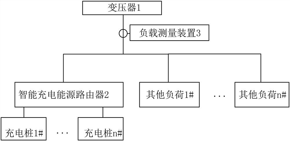
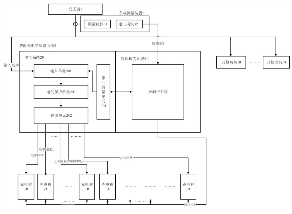
[0042] refer tofigure 1 and figure 2 shown, where figure 1 It is a schematic frame diagram of an embodiment of the power distribution coordination system based on the intelligent charging energy router 2 of the present invention. The power distribution coordination system based on the intelligent charging energy router 2 includes a transformer 1, an intelligent charging energy router 2, charging piles and other loads , the transformer 1 is used to provide power to the charging pile and other loads, the intelligent charging energy router 2 provides power to the charging pile, and also includes a load measuring device 3, wherein the intelligent charging energy router 2 includes an electrical system 20 and a management dispatching system 21, the electrical The system 20 includes an input unit 201 and an output unit 202, which are used to output the power input by the transformer 1 for use by the charging pile; the management dispatching system 21 includes a control subsystem con...

Embodiment 2

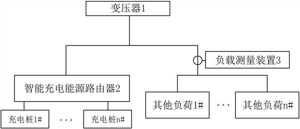
[0062] combined with image 3 , in this embodiment, there is only one load measuring device 3, which is installed on the incoming line side of other loads, and is used to measure the actual output power information of other loads. The power information received by the load measuring device 3 is the actual output power information used by other loads. Based on this, the output power that can be used by the intelligent charging energy router 2 is obtained by obtaining the actual output power of other loads and the rated power of the transformer 1. By comparing the maximum output power that the smart charging energy router 2 can use with the rated power of the smart charging energy router 2, it is confirmed that the smart charging energy router 2 limits the maximum output power. The maximum output power limited by the intelligent charging energy router 2 is used as the maximum distributed power of the charging pile, so as to enter the power control calculation of the charging pil...

Embodiment 3

[0064] combined with Figure 4 , in this embodiment, there are multiple load measuring devices 3, which are respectively arranged at the front end of each other load, and are used to measure the actual output power information of each other load and measure the total actual output power information of other loads. The power information received by the load measuring device 3 is the actual output power information used by each other load. Based on this, by obtaining the sum of the actual output power of other loads and calculating the rated power of the transformer 1, the smart charging energy router 2 can be used. For output power, by comparing the maximum output power that can be used by the smart charging energy router 2 with the rated power of the smart charging energy router 2, it is confirmed that the smart charging energy router 2 limits the maximum output power. The maximum output power limited by the intelligent charging energy router 2 is used as the maximum distribut...


PUM


Abstract

The invention discloses a power distribution cooperation system based on an intelligent charging energy router and a cooperation method thereof. The power distribution cooperation system based on theintelligent charging energy router comprises a transformer, the intelligent charging energy router, a charging pile and other loads. The system further comprises at least one load measuring device, wherein the load measuring device is used for measuring electric power information of a load in the power loop. The intelligent charging energy router receives an actual power message reported by the load measuring device, and calculates the maximum power limited and output by the intelligent charging energy router; and the intelligent charging energy router adjusts the actual control power of the connected charging pile based on the maximum output power limited by the intelligent charging energy router so as to adjust the total load of the transformer. By controlling the power of the charging pile connected with the intelligent charging energy router, the intelligent charging energy router becomes a power distribution elastic load of the transformer, so that the real-time utilization rate of power distribution resources is improved on the premise that operation safety is kept.

Description

technical field [0001] The invention relates to the technical field of charging piles, in particular to a power distribution coordination system based on an intelligent charging energy router and a coordination method thereof. Background technique [0002] With the gradual implementation of the country's new energy plan and the growing demand for the implementation and application of new energy, new energy charging stations need to continuously meet the growing demand for new energy vehicle charging piles. [0003] At present, the design of power distribution cabinet and distribution network is relatively conservative, which is not suitable for specific scenarios of charging stations. It is rare that the charging piles connected to the power distribution cabinet and distribution network are fully charged at the same time, and most of them are in low utilization conditions; the input power of commonly used power distribution cabinets and distribution networks is generally in ...

Claims


Application Information

Patent Timeline
IPC IPC(8): H02J3/32H02J3/14
CPCH02J3/14H02J3/32Y02B70/3225Y04S20/222
Inventor 曾智礼张思成郎洁
Owner SHENZHEN DINGWANG TECH CO LTD
Why Eureka
Try Eureka