An injection molding machine for industrial production

A technology of injection molding machine and injection port, which is applied in the field of injection molding machines for industrial production, can solve problems such as inaccurate measurement, plastic products not up to standard, and affecting plastic quality, so as to prevent sticking and meet quality standards

Active Publication Date: 2022-01-14
平湖市中美包装科技有限公司
View PDF15 Cites 0 Cited by
  • Summary
  • Abstract
  • Description
  • Claims
  • Application Information

AI Technical Summary

Problems solved by technology

[0003] 1. The screw used in the injection molding machine only uses a cylindrical rod outer ring to fix the helix and install the helical blade. The metering injection is realized through the reciprocating expansion and rotation of the screw. However, after one injection, the screw needs to move backward. The non-return ring at the head of the screw presses the molten material in the barrel into the metering head of the barrel under the action of back pressure. In practice, after the back pressure is fixed, the non-return ring will have wear and other losses, which will cause melting. The change of the back pressure on the plastic will affect the inaccuracy of the metering amount at this time, causing the plastic product after injection molding to fail to meet the standard;
[0004] 2. There are three sections in the barrel, and the section in the middle is the section for heating and melting the plastic. When the plastic is in the position between the feeding section and the heating section, it will be subject to temperature changes. The change is large and it will be easy This will cause the material to adhere to the screw blade and burnt at this part, which will not only affect the subsequent continuous feeding but also cause the plastic quality to decline

Method used


Image

  • An injection molding machine for industrial production
  • An injection molding machine for industrial production
  • An injection molding machine for industrial production

Examples


Embodiment Construction

[0023] The following will clearly and completely describe the technical solutions in the embodiments of the present invention with reference to the accompanying drawings in the embodiments of the present invention. Obviously, the described embodiments are only some, not all, embodiments of the present invention. Based on the embodiments of the present invention, all other embodiments obtained by persons of ordinary skill in the art without making creative efforts belong to the protection scope of the present invention.

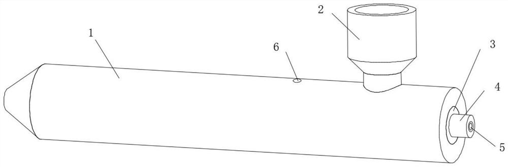
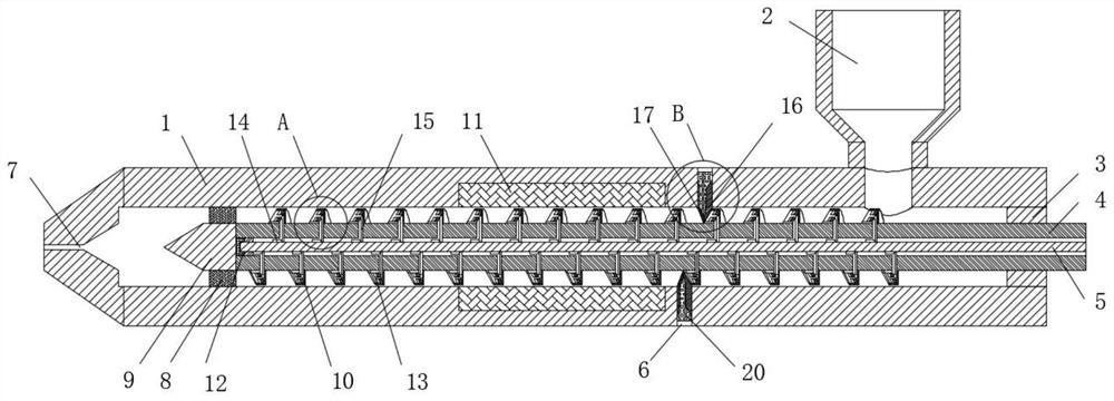
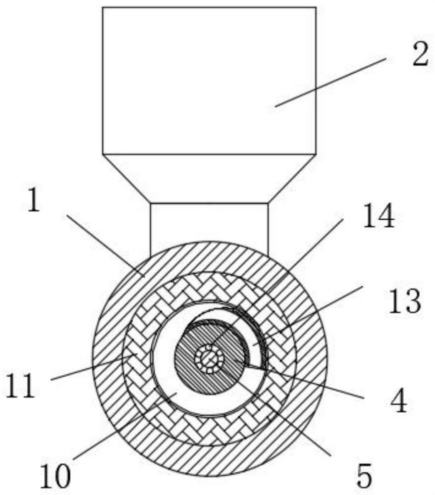
[0024] see Figure 1-5 , an injection molding machine for industrial production, comprising a barrel 1, a feed hopper 2 is fixedly installed on the top of the barrel 1, a sealing ring 3 is fixedly installed on the back of the inner ring of the barrel 1, and the inner ring of the sealing ring 3 is movably socketed There is a screw 4, the middle part of the top and bottom of the barrel 1 is provided with an exhaust hole 6, one end of the barrel 1 is provided wit...


PUM


Abstract

The invention relates to the technical field of industrial production equipment, and discloses an injection molding machine for industrial production, which includes a barrel, a feeding hopper is fixedly installed on the top of the barrel, and a sealing ring is fixedly installed on the back of the inner ring of the barrel. The inner ring of the ring is movably sleeved with a screw, the middle part of the top and bottom of the barrel is provided with an exhaust hole, one end of the barrel is provided with an injection port, and the end of the screw located at the injection port is fixedly equipped with a screw head. The outer ring of the screw located at one end of the injection port is movably sleeved with a non-reverse ring, the outer surface of the screw is screwed and fixed with a helical leaf, and a cylindrical hole is opened in the middle of the screw, and the cylindrical hole opened by the screw is located at the injection port. The inner side of one end of the mouth is movably socketed with a rubber pad head, and the middle part of the rubber pad head is fixedly installed with an inner shaft, and the side of the spiral leaf close to the injection port is movably socketed with a spiral slide bar. The injection molding machine has high injection molding efficiency. , High quality injection molding products.

Description

technical field [0001] The invention relates to the technical field of industrial production equipment, in particular to an injection molding machine for industrial production. Background technique [0002] The demand for plastics in industrial production is very large, so the equipment requirements for producing plastics are getting higher and higher to ensure high efficiency and high quality of plastic production. The existing equipment for producing plastics is injection molding machines, of which horizontal injection molding The injection molding machine is the most commonly used one. The injection molding machine uses a screw to transport the material added at one end of the barrel to the other end for injection molding. The middle part of the barrel heats and melts the material. Although the application of injection molding machines is very common, there are still With some questions: [0003] 1. The screw used in the injection molding machine only uses a cylindrical ...

Claims


Application Information

Patent Timeline
Patent Type & Authority Patents(China)
IPC IPC(8): B29C45/03B29C45/17B29C45/60B29C45/62
CPCB29C45/03B29C45/60B29C45/62B29C45/17B29C45/1753
Inventor 不公告发明人
Owner 平湖市中美包装科技有限公司
Why Eureka
Try Eureka