Single-shaft variable speed second-level asynchronous heart pump based on error term iterative curve flow channel, and use method

A curved flow and heart pump technology, applied in medical science, prosthesis, etc., can solve the problems of large pressure difference between the working surface and the back of the single-stage impeller blade, without considering the needs of different patients, blood cell destruction, etc., to achieve the reduction of blood cell The probability of hemolysis, the overall structure is favorable, the effect of reducing the intensity of turbulence

Active Publication Date: 2020-11-06
HOHAI UNIV
View PDF15 Cites 3 Cited by
  • Summary
  • Abstract
  • Description
  • Claims
  • Application Information

AI Technical Summary

Problems solved by technology

[0002] The existing known vane-type single-stage heart pumps mainly have two structural forms: axial flow and centrifugal. For the vane-type single-stage heart pump, the demand for blood pressure of the human body is all met by the lift provided by the single-stage impeller, but this will lead to single-stage The pressure difference between the working surface and the back of the impeller blade is too large, which will cause damage to blood cells and cause hemolysis. This phenomenon will become more serious with the increase of the lift.
[0003] The current research on the flow channel form of the vane single-stage heart pump is relatively simple. ZL201911056672.3 discloses a centrifugal heart pump with a low hemolysis rate. Although this type of centrifugal heart pump makes the flow in the pump body more uniform, the centrifugal heart pump The structure of the pump determines that no matter how it is improved, the blood must go through the "circular" flow in the volute before entering the outlet channel. The complex internal flow can easily cause damage to blood cells, resulting in hemolysis
ZL201910222234.3 discloses an implantable shaftless heart pump with a gradually changing flow path. A simple superposition does not take into account the actual use needs of different patients

Method used


Image

  • Single-shaft variable speed second-level asynchronous heart pump based on error term iterative curve flow channel, and use method
  • Single-shaft variable speed second-level asynchronous heart pump based on error term iterative curve flow channel, and use method
  • Single-shaft variable speed second-level asynchronous heart pump based on error term iterative curve flow channel, and use method

Examples


Embodiment 1

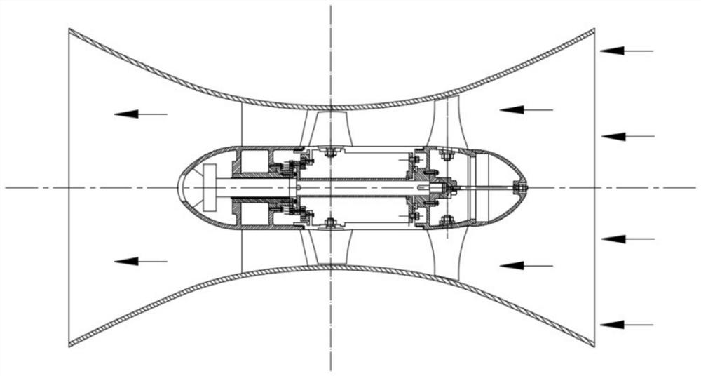
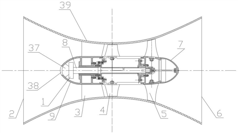
[0016] Example 1. The present invention proposes a uniaxial variable-speed two-stage asynchronous heart pump with a differential term iterative curve flow path, which includes a pump casing flow path 39 with a pump inlet 6 and a pump outlet 2, and a fixed guide is arranged in the pump casing flow path 39. The blade body 3, the first-stage impeller 5 and the second-stage impeller 4 are fixed on the transmission shaft 8 through a key; it also includes a DC permanent magnet motor 1 fixed on the inner side of the hub of the fixed guide vane body 3 through a shock absorber 37, The housing of the frequency sensor 38 is inlaid with the fixed guide vane hub tail 9 as a whole, the fixed guide vane body 3 is provided with a plurality of guide vane blades uniformly distributed around the x-axis, and the fixed guide vane body 3 passes through the guide vane The vane is fixed on the inner wall of the casing cavity of the pump casing flow channel 39;

[0017] The profile line of the casing...

Embodiment 2

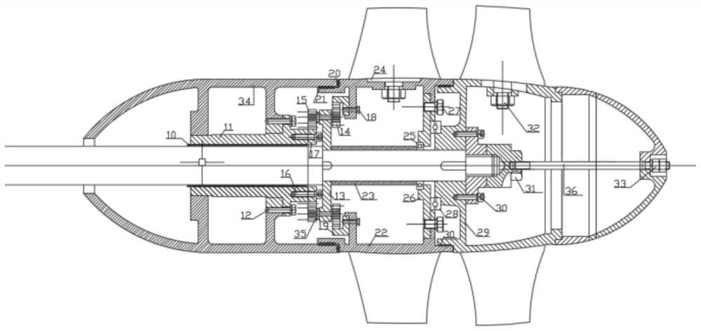
[0024] Example 2. The present invention proposes a method for using a single-axis variable-speed two-stage asynchronous heart pump with a differential term iterative curved flow channel, which is characterized in that on the basis of the above-mentioned structure of the present invention, the DC permanent magnet motor 1 is connected by the transmission shaft 8 through the key The power is transmitted to the first-stage impeller 5; the transmission shaft 8 transmits the power to the planet carrier 13 through the key, the planetary transmission gear 14 and the planetary transmission gear 15 are connected through the planetary transmission shaft 35, and the planetary transmission gear 15 and the hollow gear 17 are meshed , the planetary transmission gear 14 meshes with the ring gear 19, the ring gear 19 transmits the power to the second-stage impeller hub 22 through the fastening bolt 18, the planetary transmission gear 14, the planetary transmission gear 15, the hollow gear 17, a...

Embodiment 3

[0027] Example 3. The specific requirements for the component design, assembly and use of a single-axis variable-speed two-stage asynchronous heart pump proposed by the present invention are as follows:


PUM


Abstract

The invention relates to a single-shaft variable speed second-level asynchronous heart pump based on an error term iterative curve flow channel, and a use method. The single-shaft variable speed second-level asynchronous heart pump comprises a pump shell flow channel with a pump inlet and a pump outlet, wherein the pump shell flow channel is internally provided with a fixed guide vane body, and afirst-level impeller and a second-level impeller are fixed on a transmission shaft through keys. The single-shaft variable speed second-level asynchronous heart pump also comprises that a direct current permanent magnet motor is fixed on the inner side of a hub of the fixed guide vane body through a shock absorption supporting seat, the shell of a frequency sensor and the tail of the hub of the fixed guide vane are inlaid into a whole, the fixed guide vane body is provided with a plurality of guide vanes which are evenly distributed around an x shaft, the fixed guide vane body is fixed on theinner wall of a shell cavity of the pump shell flow channel through the guide vanes, and the molded line of the inner wall of the shell cavity is an error term iterative curve. The single-shaft variable speed second-level asynchronous heart pump has the advantages of a compact structure, a large flow, a high lift and a small injury to blood cells, a possibility of hemolysis due to the heart pump can be lowered, through a frequency sensor, the revolving speed of the pump can be changed in real time to meet a real-time requirement of the blood pressure and the blood flow of the human body.

Description

technical field [0001] The invention belongs to the technical field of fluid machinery and axial-flow heart pumps, and in particular relates to a single-axis variable-speed two-stage asynchronous heart pump with a differential term iterative curve flow channel and a use method thereof. Background technique [0002] The existing known vane-type single-stage heart pumps mainly have two structural forms: axial flow and centrifugal. For the vane-type single-stage heart pump, the demand for blood pressure of the human body is all met by the lift provided by the single-stage impeller, but this will lead to single-stage The pressure difference between the working surface and the back of the impeller blade is too large, which will cause damage to the blood cells and cause hemolysis, which will become more serious with the increase of the head. [0003] The current research on the flow channel form of the vane single-stage heart pump is relatively simple. ZL201911056672.3 discloses a...

Claims


Application Information

Patent Timeline
Patent Type & Authority Applications(China)
IPC IPC(8): A61M1/10
Inventor 戴景郑源阚阚许哲陈会向张付林戴杰
Owner HOHAI UNIV
Why Eureka
Try Eureka