Hidden lock

A concealed and lock technology, applied in the field of concealed locks, can solve the problems of rust, poor anti-theft effect of locking, corrosion of the car body, etc., to achieve the effect of improving durability, simple and neat appearance, and avoiding moisture damage.

Inactive Publication Date: 2020-11-24
TEAM YOUNG TECH CO LTD
View PDF0 Cites 0 Cited by
  • Summary
  • Abstract
  • Description
  • Claims
  • Application Information

AI Technical Summary

Problems solved by technology

[0002] Most of the existing traditional car body locks are chain locks or U-shaped locks, which are not easy to store and operate. As long as they are locked and unlocked, the user's hands will be dirty. Even if a commercially available remote control electronic lock is used, it is not only expensive Moreover, it is bulky and difficult to be accepted by users. Even the stem lock integrated with the car body affects the appearance because it is installed outside the car body, and the user still needs to manually use the key to lock and unlock it.
[0003] In addition, because the traditional locks on the car body must be equipped with keyholes, the keyholes are easily damaged by man-made, or damaged by wind, rain, and sun. In addition, traditional locks lack solid objects that can be locked together with the external environment. Mechanism, resulting in poor anti-theft effect of locking the car body as a whole
The commercially available remote control electronic lock is also equipped with a battery. When the car body is parked or ridden in a bad environment, the battery in the electronic lock will be damaged by moisture, and the leaked battery liquid will cause the car body to corrode or rust. And when the electronic lock has no power, the battery must be replaced, which is very inconvenient for the user

Method used


Image

  • Hidden lock
  • Hidden lock
  • Hidden lock

Examples


Embodiment Construction

[0041] In the following, various preferred embodiments according to the present invention are enumerated in conjunction with the drawings to describe the components disclosed in the present invention and the effects achieved. However, the components, dimensions and appearance of the menu setting device shown in each figure are only used to illustrate the technical features of the present invention, rather than constituting a limit to the present invention.

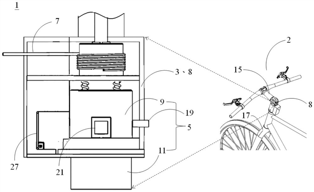
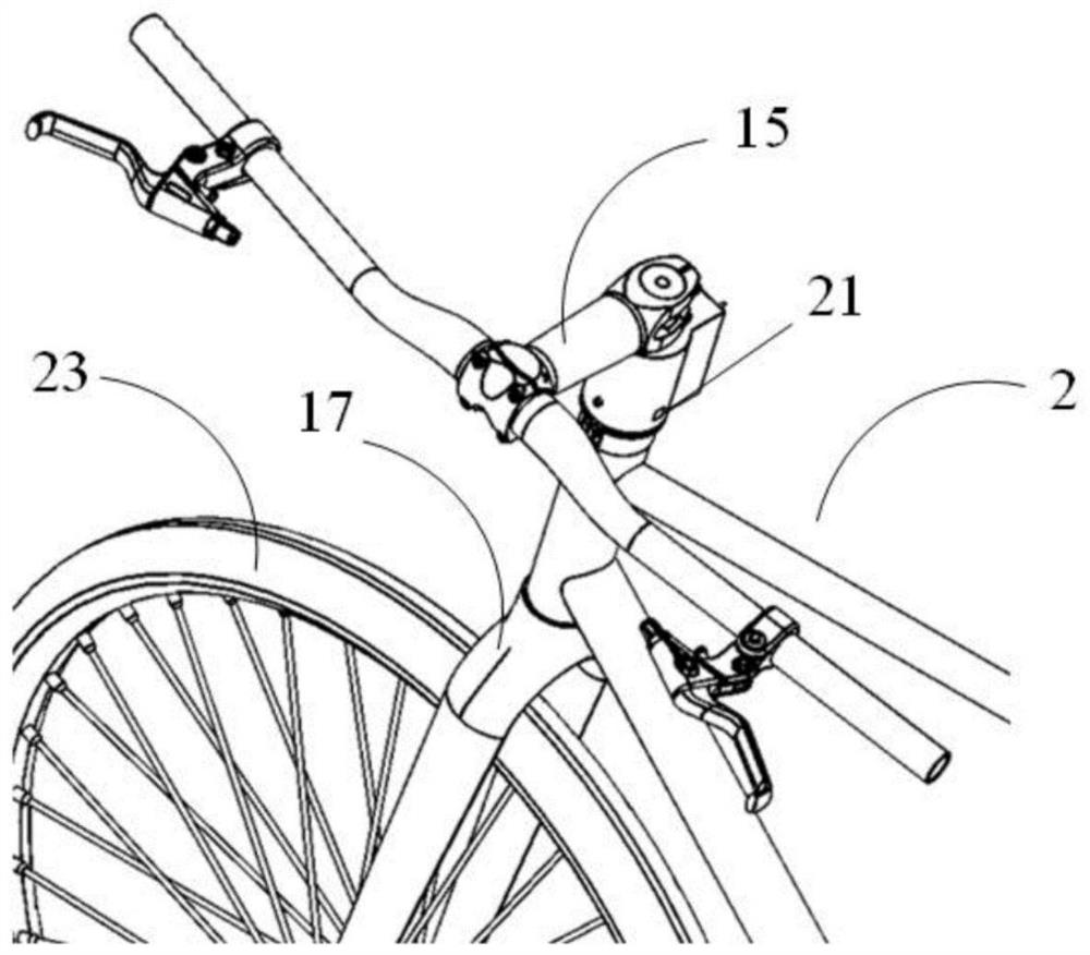
[0042] First, please refer to figure 1 , which is a schematic diagram of the concealed lock located on the vehicle body of the present invention. Such as figure 1 As shown, the concealed lock 1 of the present invention includes a cavity 3, a lock body 5 and a lock wire 7 for performing a locked state (not shown) or an unlocked state of the vehicle body 2 (such as a bicycle). status (not shown). The lock body 5 is placed in the lumen 3 (or, for example, the head pipe 8 of the vehicle body 2 ), and has a first lock piece ...


PUM


Abstract

The invention provides a hidden lock. The hidden lock is used for executing the locking state or the unlocking state of a vehicle body and comprises a cavity tube, a lock body and a locking wire; thelock body is arranged in the cavity tube and comprises a first lock piece and a second lock piece; the first lock piece and the second lock piece are connected with a handle and a front fork of the vehicle body; the linkage state exists between the first lock piece and the second lock piece; the locking wire is arranged in the cavity tube, is located at one end of the lock body, telescopes insideand outside the cavity tube and corresponds to a buckle arranged on at least one of the lock body and the vehicle body; and the embedment state exists between the locking wire and the buckle. The locking state or the unlocking state of the vehicle body is decided by at least one of the linkage state of the lock body and the embedment state of the locking wire. The lock can be combined with the vehicle body and does not have significant appearances of traditional locks.

Description

technical field [0001] The invention relates to a lock, in particular to a hidden lock. Background technique [0002] Most of the existing traditional car body locks are chain locks or U-shaped locks, which are not easy to store and operate. As long as they are locked and unlocked, the user's hands will be dirty. Even if a commercially available remote control electronic lock is used, it is not only expensive Moreover, it is bulky and difficult to be accepted by users. Even the stem lock integrated with the car body affects the appearance because it is installed outside the car body, and the user still needs to manually use the key to lock and unlock it. [0003] In addition, because the traditional locks on the car body must be equipped with keyholes, the keyholes are easily damaged by man-made, or damaged by wind, rain, and sun. In addition, traditional locks lack solid objects that can be locked together with the external environment. Mechanism, and cause the overall loc...

Claims


Application Information

Patent Timeline
Patent Type & Authority Applications(China)
IPC IPC(8): B62H5/06
CPCB62H5/06
Inventor 刘彦亨
Owner TEAM YOUNG TECH CO LTD
Why Eureka
Try Eureka