A new type of pipe grinding device

A pipeline and a new type of technology, applied in the direction of grinding drive devices, grinding machines, grinding slides, etc., can solve the problems of affecting the health of workers, high labor intensity, and dust prone to grinding, achieving less manpower consumption, high grinding efficiency, The effect of increasing the grinding area

CN112059760BActive Publication Date: 2021-02-02YANTAI ENG & TECH COLLEGE YANTAI TECHNICIAN INST
7 Cites 0 Cited by

Patent Information

Authority / Receiving Office
CN · China
Patent Type
Patents(China)
Current Assignee / Owner
Publication Date
2021-02-02

Smart Images

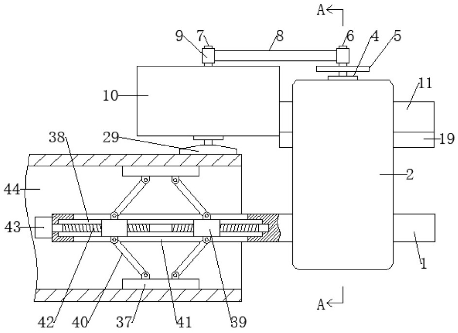
  • Figure 1
    Figure 1
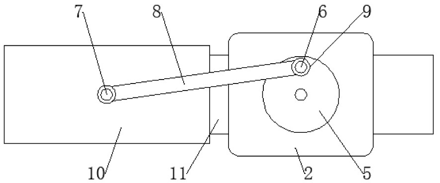
  • Figure 2
    Figure 2
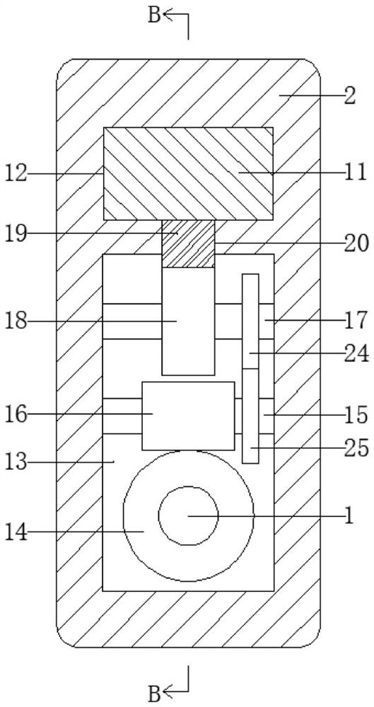
  • Figure 3
    Figure 3
Patent Text Reader

Abstract

The invention relates to the technical field of grinding devices, in particular to a new type of pipeline grinding device. One end of the central shaft is provided with a pipeline support mechanism, and the other end of the central shaft is rotatably mounted with a rotating seat, which is slidably installed along the length direction of the central shaft. There is a support frame, a grinding mechanism is provided on the support frame, a first small shaft is fixedly installed eccentrically on the drive disc, a second small shaft parallel to the first small shaft is fixedly mounted on the support frame, the first small shaft and the second small shaft A connecting rod is arranged between the shafts; when the driving disc of the present invention rotates, the connecting rod drives the grinding mechanism to reciprocate along the length direction of the pipeline to increase the grinding area of ​​the grinding mechanism. When the driving gear rotates against the rotation direction of the ratchet, Drive the rotating seat to rotate a certain angle around the central axis to increase the grinding process. When the driving gear rotates along the rotation direction of the ratchet, the rotating seat and the central axis remain relatively static to increase the contact time between the grinding mechanism and the same part of the pipeline.
Need to check novelty before this filing date? Find Prior Art

Description

technical field

[0001] The invention relates to the technical field of grinding devices, in particular to a novel pipeline grinding device. Background technique

[0002] When natural gas pipelines are installed, the joints will be polished and derusted to make the sealing better. However, when the natural gas pipelines are polished manually with grinding tools, the labor intensity is high, and dust is easy to appear during grinding, which affects the health of workers. Therefore, it is urgently needed Develop a pipe grinding device that saves time and effort and has a good grinding effect. Contents of the invention

[0003] The technical problem to be solved by the present invention is to provide a novel pipeline grinding device, which consumes less manpower and has good grinding effect, so as to solve the problems in the prior art.

[0004] In order to solve the above technical problems, the technical solution of the present invention is: a novel pipe grinding device, co...

Examples

Embodiment Construction

[0019] Such as Figure 1 to Figure 6 As shown, a new type of pipe grinding device includes a central shaft 1, one end of the central shaft 1 is provided with a pipe support mechanism, and the other end of the central shaft 1 is rotatably mounted with a rotating seat 2, on which the rotating seat 2 A support frame 3 is slidably installed along the length direction of the central axis 1, and a grinding mechanism is arranged on the support frame 3; a driving motor 4 is fixedly installed on the rotating base 2, and the rotation axis of the driving motor 4 is perpendicular to The central shaft 1 and the rotating shaft of the driving motor 4 are coaxially fixed with a drive disc 5, and the first small shaft 6 is fixedly mounted eccentrically on the drive disc 5, and the support frame 3 is fixedly mounted with a The first small shaft 6 is parallel to the second small shaft 7, a connecting rod 8 is arranged between the first small shaft 6 and the second small shaft 7, and the two ends...