An aerial work vehicle chassis with multi-directional movement of the aerial work platform

A high-altitude operation vehicle and high-altitude operation technology, which is applied to vehicle components, lifting devices, and lower structures, can solve problems such as rotation obstruction, inability to deliver the workbench to the designated position, and long crank arm length, etc., to achieve the effect of improving safety

Active Publication Date: 2022-03-11
万全重工(常州)机械有限公司
View PDF6 Cites 0 Cited by
  • Summary
  • Abstract
  • Description
  • Claims
  • Application Information

AI Technical Summary

Problems solved by technology

[0004] The purpose of the present invention is to provide an aerial work vehicle chassis with multi-directional movement of the aerial work platform, so as to solve the problem in the above background technology that the existing crank arm length is long, and the rotation in some narrow spaces is hindered, and the work platform cannot be moved. Sent to the specified location, causing troublesome problems

Method used


Image

  • An aerial work vehicle chassis with multi-directional movement of the aerial work platform
  • An aerial work vehicle chassis with multi-directional movement of the aerial work platform
  • An aerial work vehicle chassis with multi-directional movement of the aerial work platform

Examples


Embodiment 1

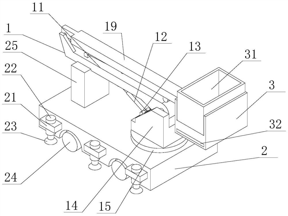
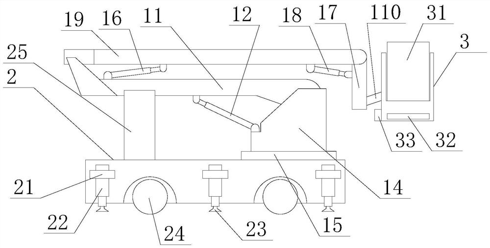
[0022] Embodiment 1: refer to Figure 1-Figure 2 , the bottom of the chassis 2 is provided with mutually symmetrical wheels 24, the quantity of the wheels 24 is provided with four, the two sides of the chassis 2 are movably connected with mutually symmetrical telescopic plates 21, and the quantity of the telescopic plates 21 is provided with six, increasing the chassis 2 Stability, the inside of the telescopic plate 21 is fixedly connected with a leg 22, the bottom of the leg 22 is provided with a grounding plate 23, the top of the grounding plate 23 is fixedly connected with the bottom surface of the leg 22, and the top of the chassis 2 is provided with a recovery support plate 25, recycling The bottom surface of the support plate 25 is fixedly connected to the top of the chassis 2. This design enables the boom 11 to play a certain supporting role when it is recovered, so as to avoid damage to the boom 11 due to inertia. The bottom surface of the slewing support 15 and the top...

Embodiment 2

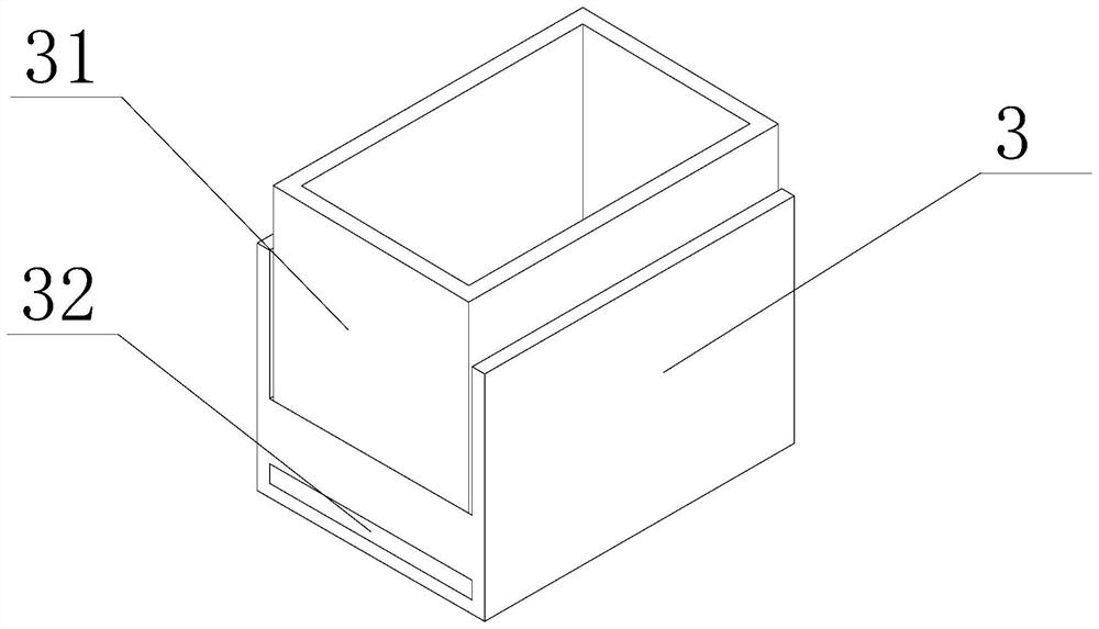
[0023] Embodiment 2: refer to Figure 3-Figure 5, the top of the workbench base 3 is provided with a groove running through the front and the back, the groove of the workbench base 3 is provided with a workbench 31, the bottom surface of the workbench 31 is movably connected with the groove bottom surface of the workbench base 3, and the workbench The bottom surface of 31 is fixedly connected with connecting block one 35, and the bottom of workbench 31 is provided with screw mandrel 39, and the quantity of screw mandrel 39 is provided with two and is vertically distributed up and down, and one end of screw mandrel 39 is connected with the inwall of workbench base 3 by rotation , the other end of screw mandrel 39 is fixedly connected with DC motor one 36, and the bottom of DC motor one 36 is fixedly connected with connection seat, and connection seat is fixedly connected with the inner wall of workbench base 3 by bolt, and DC motor one 36 is connected with work through connectio...


PUM


Abstract

The invention discloses an aerial work vehicle chassis with multi-directional movement of an aerial work platform, relates to the technical field of aerial work equipment, and includes a crank arm mechanism. The side is fixedly connected with the base of the workbench. The crank arm mechanism includes a boom. A vertical arm is arranged below the boom. The top of the vertical arm is provided with a slot, and the two sides of the vertical arm slot pass through The connecting shaft is rotatably connected with the big arm, and a slewing support is provided under the vertical arm. In the present invention, the workbench is slidingly connected to the workbench base and the groove, so that the present invention directly extends the movable distance in the horizontal direction through the movement of the workbench when in use, and does not need to achieve horizontal movement through the rotation of the crank arm , Adapt to a variety of working environments, and solve the troublesome problem that the workbench cannot be sent to the designated position due to the long length of the crank arm, which hinders the rotation in some narrow spaces.

Description

technical field [0001] The invention relates to an aerial work vehicle, relates to the technical field of aerial work equipment, in particular to a chassis of an aerial work vehicle with multi-directional movement of an aerial work platform. Background technique [0002] Aerial work vehicle refers to a special vehicle that transports staff and equipment to the site and performs aerial work. According to the form of its lifting mechanism, it can generally be divided into telescopic arm type (straight arm type), folding arm type (curved arm type), There are four basic forms of vertical lift type and hybrid type. The crank arm type aerial work vehicle is easy to move and the crank arm structure is compact. It adopts new high-quality steel, high strength, light weight, directly connected to AC or started by the vehicle's own power, and the erection speed is fast. Fast, with a telescopic arm, the workbench can be raised and extended, and can also be rotated 360 degrees. It is eas...

Claims


Application Information

Patent Timeline
Patent Type & Authority Patents(China)
IPC IPC(8): B66F11/04B66C23/683B66C23/78B62D21/18
CPCB66F11/044B66C23/68B66C23/78B62D21/18
Inventor 沈灵
Owner 万全重工(常州)机械有限公司
Why Eureka
Try Eureka