Gear blackening frame for machining

A technology of mechanical processing and gears, which is applied in the field of blackening racks, can solve problems such as laboriousness, and achieve comprehensive and uniform blackening with good effects

Pending Publication Date: 2020-12-25
黄秀荣
View PDF0 Cites 0 Cited by
  • Summary
  • Abstract
  • Description
  • Claims
  • Application Information

AI Technical Summary

Problems solved by technology

[0005] In order to overcome the disadvantages that the sides of the gears in contact with each other cannot be contacted with the blackening liquid for blackening, and the gears are stirred with a rod to make the blackening uniform, and the hand needs to be constantly moved, which is relatively laborious. The technical problem of the present invention is: Provide a gear blackening rack for machining that can completely blacken the gears, and can drive the gears to rotate, blacken uniformly, require no human operation, and save labor

Method used


Image

  • Gear blackening frame for machining
  • Gear blackening frame for machining
  • Gear blackening frame for machining

Examples


Embodiment 1

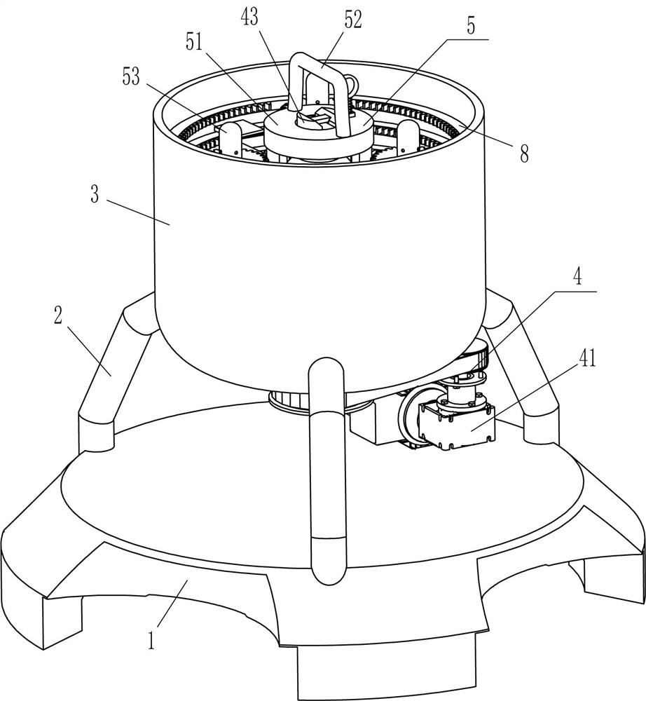
[0025] A gear blackening frame for mechanical processing, such as Figure 1-Figure 3 As shown, it includes a base 1, a pole 2, a charging cylinder 3, a rotating mechanism 4, a discharging mechanism 5 and a push plate 6, and the top of the base 1 is fixedly connected with three poles 2 at uniform intervals in the circumferential direction, and three poles 2 A charging cylinder 3 is fixedly connected between the top ends, a rotating mechanism 4 is arranged between the middle part of the charging cylinder 3 and the top rear side of the base 1, and a discharging mechanism 5 is placed between the rotating mechanism 4 and the middle part of the charging cylinder 3. The mechanism 5 cooperates with the rotating mechanism 4, and the inner surface of the charging cylinder 3 is fixedly connected with push plates 6 evenly spaced circumferentially, and the number of each row of push plates 6 is five.

[0026] The rotating mechanism 4 includes a decelerating motor 41, a transmission assembl...

Embodiment 2

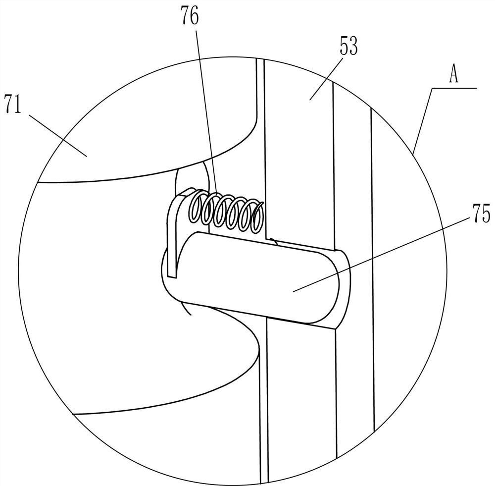
[0032] On the basis of Example 1, such as Figure 4 and Figure 5 As shown, also includes clamping mechanism 7, and clamping mechanism 7 includes driving rod 71, first spring 72, contact rod 73, three-groove fixed ring 74, clamping rod 75 and second spring 76, charging cylinder 3 middle parts There is a three-slot fixed ring 74 in the inner circumferential fixed sleeve, and the inner sliding type of the bottom of the L-shaped plate 54 is provided with a contact rod 73, and the inner end of the contact rod 73 is in contact with the three-slot fixed ring 74. Rod 71, the first spring 72 is connected between the top of the driving rod 71 and the inner top of the hollow rod 53, the bottom end of the driving rod 71 is in contact with the outer end of the contact rod 73, and the hollow rod 53 is evenly spaced in the circumferential direction. The clamping rod 75 that can be fixed to the gear, the internal end of the clamping rod 75 contacts and cooperates with the drive rod 71 , and...

Embodiment 3

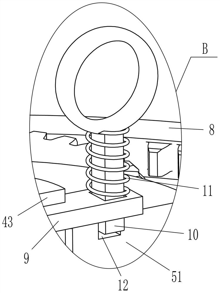
[0035] On the basis of embodiment 1 and embodiment 2, such as figure 1 , figure 2 and Figure 6 As shown, an inner gear 8 is also included, five inner gears 8 are affixed to the inner surface of the charging cylinder 3 at even intervals in the circumferential direction, and the inner gears 8 and the push plates 6 are alternately arranged.

[0036] Also include clamping plate 9, pull rod 10 and the 3rd spring 11, snap ring 51 top right side has draw-in groove 12, rotating shaft 43 upper sliding type is provided with clamping plate 9, and clamping plate 9 right part sliding type wears and connects with Pull rod 10, the bottom end of pull rod 10 is located in the slot 12 to cooperate with it, and a third spring 11 is wound between the top of pull rod 10 and the right side of the top of clamp plate 9.

[0037] When the hollow rod 53 drives the gear to reverse, when the gear reverses and meshes with the ring gear 8, the ring gear 8 makes the gear rotate, and the gear rotates to ...


PUM


Abstract

The invention relates to a blackening frame, in particular to a gear blackening frame for machining. The gear blackening frame for machining is used for achieving the technical purposes that the framecan drive gears to rotate, blackening is uniform, and labor is saved because no manual operation. The gear blackening frame for machining comprises a base and a charging barrel. Three supporting rodsare fixedly connected to one side of the base in the circumferential direction at intervals, and the charging barrel is fixedly arranged among the ends, far away from the base, of the three supporting rods in a connected manner. According to the gear blackening frame for machining, the proper quantity of blackening liquid is poured into the charging barrel, a hollow rod is sleeved with the gears,the gears make contact with the blackening liquid, a gear motor is started up to make the gears rotate reversely to be blackened, and the sides, making contact with each other, of every two adjacentgears can make contact with the blackening liquid through the scraper blade to be blackened all around. Therefore, the situation that the sides, making contact with each other, of two adjacent gears cannot be blackened can be avoided, blackening is comprehensive and uniform, the gears do not need to be stirred manually, and labor is saved.

Description

technical field [0001] The invention relates to a blackening stand, in particular to a gear blackening stand for mechanical processing. Background technique [0002] A gear is a mechanical element with gears on the rim that continuously mesh to transmit motion and power. The application of gears in transmission has appeared very early. At the end of the 19th century, the principle of generative gear cutting method and special machine tools and tools for gear cutting using this principle appeared one after another. With the development of production, the stability of gear operation was paid more attention. When the gear was produced, in order to avoid the subsequent use of the gear If it gets rusty, the gears will be put into the blackening solution for blackening to form a protective film. [0003] At present, most of the gears are directly thrown into the blackening solution for blackening by people. Due to the large number of gears, they are easy to be stacked when throw...

Claims


Application Information

Patent Timeline
Patent Type & Authority Applications(China)
IPC IPC(8): C23C22/73
CPCC23C22/73
Inventor 黄秀荣
Owner 黄秀荣
Why Eureka
Try Eureka