Gear finish machining device and method

A processing device and gear refinement technology, which is applied to gear tooth manufacturing devices, metal processing equipment, belts/chains/gears, etc., can solve the problem of long grinding time in the grinding process, weakening of the life of the gear grinding machine, and high difficulty of grinding. and other problems, to achieve the effect of simple and fast installation, improved accuracy and improved work efficiency

Inactive Publication Date: 2021-03-12
CHONGQING XINGJI GEAR
View PDF5 Cites 0 Cited by
  • Summary
  • Abstract
  • Description
  • Claims
  • Application Information

AI Technical Summary

Problems solved by technology

[0003] At present, in the process of finishing the heat-treated gear, due to the instability of the material used to manufacture the gear or the deformation after heat treatment, in order to ensure the smooth progress of the later finishing, it is necessary to reserve a large grinding allowance , can correct the deformation of the gear after heat treatment and improve the precision of the gear. However, after increasing the gear grinding allowance, it is easy to cause a large difficulty coefficient of gear grinding, which seriously weakens the life of the gear grinding machine, and it is easy to cause the grinding time of the gear grinding process. Special features, seriously reduce the grinding efficiency and lead to low processing efficiency
[0004] In addition, in the prior art, when finishing a large number of gears, the gears need to be clamped and fixed to avoid the gears from shifting and affecting the machining accuracy of the gears. In the prior art, the centering shaft is used for clamping. During the clamping process, the gear needs to be interspersed on the mandrel, and then it needs to be fixed by a nut. After the gear is processed, the nut needs to be loosened to take out the gear. It is troublesome to use the method in the prior art, and it needs to be tightened when installing the gear. The nut needs to be loosened when taking out the gear, which is very time-consuming and labor-intensive, and the work efficiency is low

Method used


Image

  • Gear finish machining device and method
  • Gear finish machining device and method
  • Gear finish machining device and method

Examples


Embodiment 1

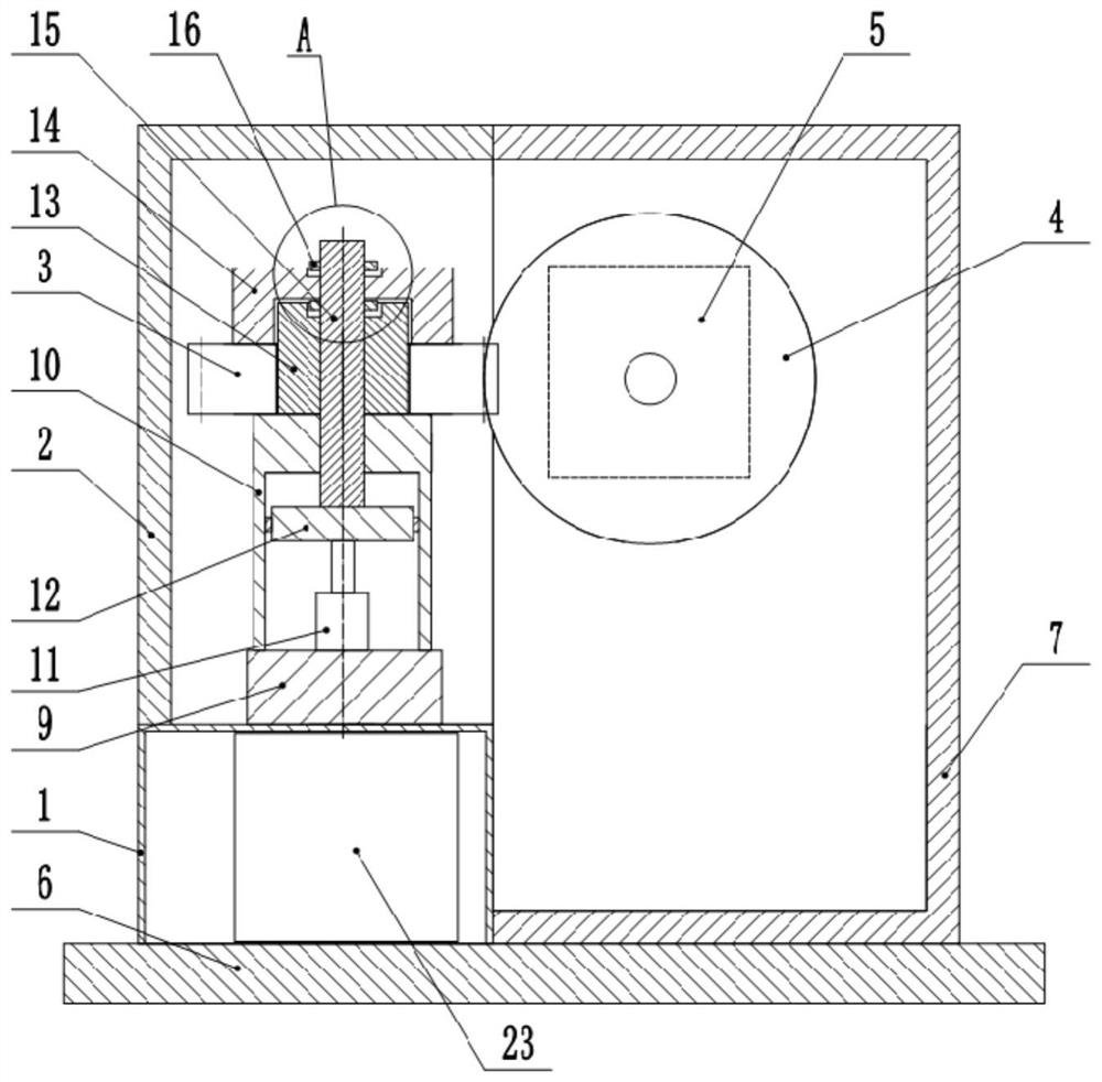
[0036] The embodiment is basically as attached figure 1 Shown: the gear finishing device includes a tool installation unit and a gear installation unit. The tool installation unit includes a frame 7 and a tool. The frame 7 is equipped with a driver 5 for driving the tool. The tool in this embodiment is a grinding wheel 4 , the driving part 5 is used to drive the grinding wheel 4 to move up and down reciprocally, and the driving part 5 can adopt the driving parts such as gear and rack mechanism, hydraulic cylinder and so on in the prior art.

[0037] In this embodiment, the gear installation unit includes a mounting table 1 and a clamp. A rotating part that drives the clamp to rotate is installed on the mounting table 1. In this embodiment, a motor is used for the rotating part. In this embodiment, a bottom plate 6 is also provided at the bottom of the mounting table 1. The mounting table 1 is slidably connected to the base plate 6, and the mounting table 1 is provided with a p...

Embodiment 2

[0050] Such as Figure 5 As shown, the difference between the gear finishing device and Embodiment 1 is that in this embodiment, an annular groove 24 is provided on the top of the fixed column 13, and four segmented blocks 25 are welded and fixed in the annular groove 24. The four segmented blocks 25 Evenly distributed along the circumferential direction of the annular groove 24 .

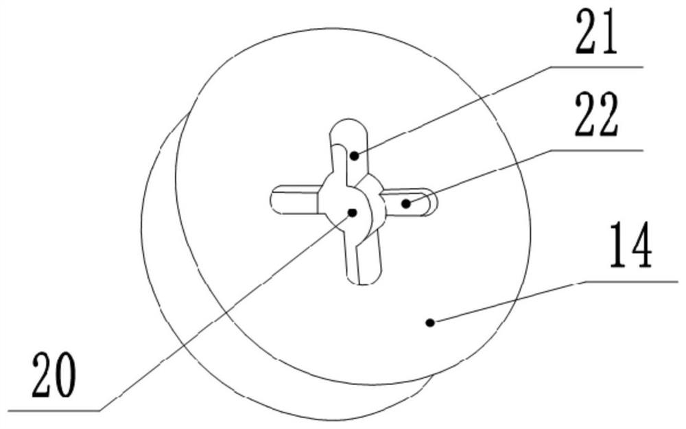
[0051] Such as Image 6 As shown, the bottom end of the cover 14 is integrally formed with four moving blocks 26, the four moving blocks 26 are evenly distributed along the circumferential direction of the cover 14, and the four moving blocks 26 can be inserted into the annular groove 24, and when the four When the moving blocks 26 are respectively inserted into the annular grooves 24 between the adjacent partition blocks 25 and are respectively against the four partition blocks 25, the through groove 21 on the blocking cover 14 is opposite to the stop block 16 on the positioning shaft 15. It is ...


PUM


Abstract

The invention relates to the field of gear machining, and discloses a gear finish machining device. The gear finish machining device comprises a cutter mounting unit and a gear mounting unit, whereinthe gear mounting unit comprises a mounting table and a fixture; a rotating piece for driving the fixture to rotate is mounted on the mounting table; the fixture comprises a support box, a fixed column, a positioning shaft and a stop cover; the fixed column is positioned at the top end of the support box, and is fixedly connected with the support box; the bottom of the positioning shaft penetratesthrough the top end of the support box; the top end of the positioning shaft penetrates through the top end of the fixed column, and is in vertical sliding fit with the fixed column; a gear is inserted in the outer side of the fixed column; the stop cover can cover the upper part of the fixed column; the stop cover is provided with a first shaft hole for penetrating through the positioning shaft;a limiting block is arranged at the upper part of the positioning shaft; a lifting unit for driving the positioning shaft to vertically move back and forth is mounted in the support box; when the positioning shaft downwards moves, the limiting block can press the stop cover; and the stop cover is provided with a through groove for penetrating through the limiting block. The gear finish machiningdevice can improve the gear grinding efficiency, and is fast and convenient to clamp the gear.

Description

technical field [0001] The invention relates to the field of gear processing, in particular to a gear finishing device and method. Background technique [0002] At present, in the process of processing gears, it is necessary to process the tooth shape of the gear first, and then heat treat the gear. At present, the processing requirements for the gear are getting higher and higher. Therefore, in order to improve the precision of the gear, the gear after heat treatment needs to be ground. Finishing process after heat treatment of gears, honing gears, etc. [0003] At present, in the process of finishing the heat-treated gear, due to the instability of the material used to manufacture the gear or the deformation after heat treatment, in order to ensure the smooth progress of the later finishing, it is necessary to reserve a large grinding allowance , can correct the deformation of the gear after heat treatment and improve the precision of the gear. However, after increasing t...

Claims


Application Information

Patent Timeline
Patent Type & Authority Applications(China)
IPC IPC(8): B23F19/00B23F23/06
CPCB23F19/00B23F23/06
Inventor 黎梅陈干戚太龙
Owner CHONGQING XINGJI GEAR
Why Eureka
Try Eureka