Reciprocating magnetic positioning motor

A magnetic positioning and reciprocating technology, applied in electrical components, electromechanical devices, electric components, etc., can solve the problems of high production circuit cost, many transmission links, shortened service life, etc., to achieve simple and convenient control, and simplify the structure of components and structures Simple and compact effect

Pending Publication Date: 2021-04-06
江门市胜思特电器有限公司
View PDF0 Cites 1 Cited by
  • Summary
  • Abstract
  • Description
  • Claims
  • Application Information

AI Technical Summary

Problems solved by technology

[0003] However, when it needs to be applied to multi-point massage massage equipment that is in contact with the human body in a large area and pays attention to the sense of touch, the mechanical connection structure driven by the rotating motor makes the intermediate energy conversion and transmission links more, the loss is large, and the efficiency is low. Most of the rotating motors are brushed motors. Continuous use will cause serious wear and tear of the motor, reduce the service life, and have a large volume; the linear reciprocating motor circuit with multiple sets of stator winding

Method used


Image

  • Reciprocating magnetic positioning motor
  • Reciprocating magnetic positioning motor
  • Reciprocating magnetic positioning motor

Examples


Embodiment Construction

[0020] The technical solutions of the present invention will be clearly and completely described below in conjunction with the embodiments. Apparently, the described embodiments are only some of the embodiments of the present invention, not all of them. Based on the embodiments of the present invention, all other embodiments obtained by persons of ordinary skill in the art without creative efforts fall within the protection scope of the present invention.

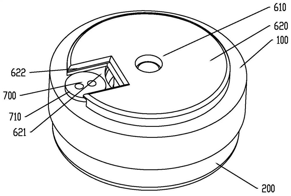
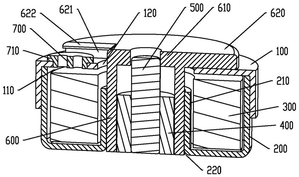
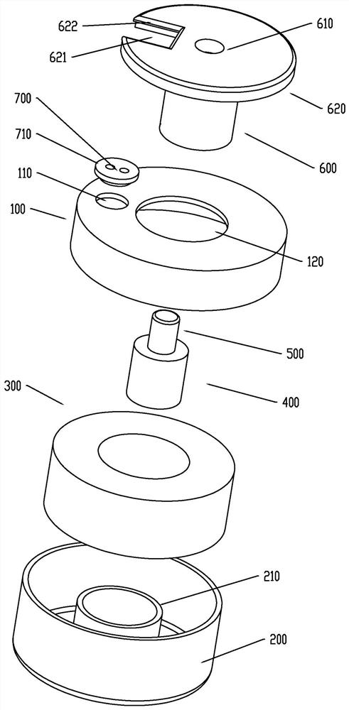
[0021] Such as Figure 1 to Figure 3 As shown, the reciprocating magnetic positioning motor includes a magnetically conductive top cover 100, a magnetically conductive bottom case 200, a stator coil 300, a permanent magnet moving core 400, and a colloidal bushing 600, and the edge of the magnetically conductive top cover 100 is fastened to the magnetically conductive bottom case 200. An installation cavity is formed, and a stator coil 300 is arranged in the installation cavity. The bottom of the magnetically permeable botto...


PUM


Abstract

The invention provides a reciprocating magnetic positioning motor, which comprises a magnetic conductive top cover, a magnetic conductive bottom shell, a stator coil, a permanent magnet moving core and a colloid bushing. The edge of the magnetic conductive top cover is buckled with the magnetic conductive bottom shell to form a mounting cavity, and the stator coil is arranged in the mounting cavity. The bottom of the magnetic conductive bottom shell and the top of the magnetic conductive top cover are respectively provided with a first through hole and a second through hole corresponding to the central axis of the stator coil, and two ends of the colloid bushing are respectively inserted into the first through hole and the second through hole at the bottom of the magnetic conductive bottom shell and the top of the magnetic conductive top cover. The permanent magnet moving core is slidably arranged in the colloid bushing and connected with a push rod slidably extending out of the top end of the colloid bushing, and a reset magnetic conductive ring sleeve used for enabling the permanent magnet moving core to slidably reset is arranged at the edge of the second through hole at the bottom of the magnetic conductive bottom shell and surrounds the outer wall of the colloid bushing towards the interior of the mounting cavity. An annular notch is formed between the top surface of the reset magnetic conductive ring sleeve and the bottom surface of the magnetic conductive top cover. The reciprocating type magnetic positioning motor provided by the invention is simple and compact in structure, high in reliability and simple and convenient to control.

Description

technical field [0001] The invention relates to the technical field of motors, in particular to reciprocating magnetic positioning motors. Background technique [0002] Existing massage equipment such as facial massagers, foot massagers, massage chairs and massage guns, etc., the massage action part of the massage equipment is mainly driven by the reciprocating motion converted by the crank linkage mechanism driven by the rotating motor, or directly by The reciprocating mover of the reciprocating motor is directly reciprocatingly driven, and the linear reciprocating motor used is usually composed of multiple sets of stator windings and diodes to generate an alternating magnetic field to drive the reciprocating mover to frequently change direction to achieve linear reciprocating motion, or a single set of windings with such as a return spring , reset magnets, etc. drive the reciprocating mover to change direction frequently to realize linear reciprocating motion. [0003] Ho...

Claims


Application Information

Patent Timeline
IPC IPC(8): H02K33/10H02K5/24H02K5/10
CPCH02K5/10H02K5/24H02K33/10
Inventor 张炯张家驹
Owner 江门市胜思特电器有限公司
Why Eureka
Try Eureka