Release equipment

A technology of throwing hands and locking parts, which is applied in the direction of wellbore/well parts, earthwork drilling and production, etc. It can solve the problems of poor working stability, complex locking mechanism structure, easy to get out of the locked state, etc., and achieves easy processing and manufacturing, The effect of improving reliability and stability and simplifying steps

Active Publication Date: 2017-01-04
CHINA PETROLEUM & CHEM CORP +1
View PDF6 Cites 0 Cited by
  • Summary
  • Abstract
  • Description
  • Claims
  • Application Information

AI Technical Summary

Problems solved by technology

[0004] The technical problem to be solved by the present invention is to overcome the disadvantages of complex structure, poor working stability and easy departure from the locked state in the locking mechanism in the prior art.

Method used


Image

  • Release equipment
  • Release equipment
  • Release equipment

Examples


Embodiment Construction

[0024] The present invention will be further described below in conjunction with accompanying drawing.

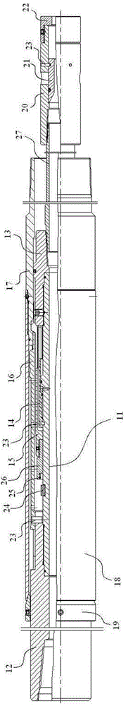
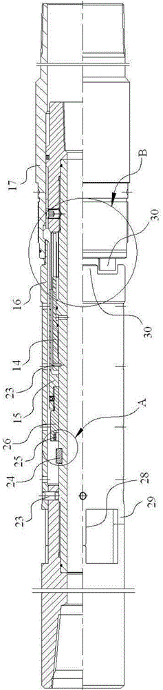
[0025] figure 1 The structure of the embodiment of the hands-dropping device of the present invention is schematically shown. figure 2 Schematically shows the structure of the throwing mechanism of the present invention.

[0026] Such as figure 1 Shown, the embodiment of the hand-dropping device of the present invention mainly includes a hand-dropping mechanism, a protective structure and a removable ball seat. Wherein, the hand-losing mechanism includes a mandrel 11 , an upper joint 12 , a lower joint 13 , a locking mechanism, a hydraulic cylinder 14 , a sleeve 15 , a torque sleeve 16 and a torque joint 17 . The protection structure includes a protection piece 18 and a protection piece 19, wherein, in one embodiment, the protection piece 18 is a protection cylinder, and the protection piece 19 is a sand-proof cap. The ball seat includes a ball seat shell 20 , a ball s...


PUM


Abstract

The invention discloses release equipment comprising the following units: a mandrel; a first locking member fixedly sleeved on an outer circumferential surface of the mandrel; a sleeve sleeved on the outer circumferential surface of the mandrel and capable of moving in the axial direction of the mandrel; a first connector detachably connected with one end, close to the first locking member, of the sleeve; a second locking member detachably connected with one end, close to the first locking member, of the first connector, wherein when the first and second locking members are matched and locked, the first connector and the sleeve can be limited from moving in the axial direction of the mandrel. The release equipment can use more stable and reliable locking mechanism to ensure the release work to be smoothly done, thus improving working efficiency of the release work.

Description

technical field [0001] The invention relates to the technical field of oil field drilling, in particular to a hands-free device. Background technique [0002] The hand drop device is a device widely used in oilfield drilling equipment. The hands-off device is used to feed the pipe string into the well. After the hands-off device carries the pipe string to the predetermined position in the well, it needs to separate the pipe string from the hands-off device by completing the hands-off work. The detached tubing string is left in the well at its intended location. [0003] According to the long-term observation and research of the inventors of the present application, it is found that the currently used locking mechanism has the disadvantages of complicated structure, poor working stability and easy departure from the locked state, especially when the performance of drilling fluid in oil wells is relatively low. Poor, if there is no protection on the outside of the hydraulic...

Claims


Application Information

Patent Timeline
Patent Type & Authority Applications(China)
IPC IPC(8): E21B23/00
Inventor 侯乃贺阮臣良吴晋霞孙文俊陈武君李夯张瑞
Owner CHINA PETROLEUM & CHEM CORP
Why Eureka
Try Eureka