Grinding equipment for plate grinding compounding

A technology for grinding and sheet metal, which is applied in the direction of grinding/polishing equipment, parts of grinding machine tools, machine tools suitable for grinding workpiece planes, etc. It can solve the problems affecting the production efficiency of sheet metal, long time consumption, and difficulties in multiple surfaces

Pending Publication Date: 2021-04-30
CHONGQING UNIV +1
View PDF0 Cites 0 Cited by
  • Summary
  • Abstract
  • Description
  • Claims
  • Application Information

AI Technical Summary

Problems solved by technology

However, there will be problems such as low processing efficiency and insufficient automation.
Generally speaking, the traditional surface grinder can only grind one surface of the plate, and it is very difficult to grind multiple surfaces at the same t

Method used


Image

  • Grinding equipment for plate grinding compounding
  • Grinding equipment for plate grinding compounding
  • Grinding equipment for plate grinding compounding

Examples


Embodiment 1

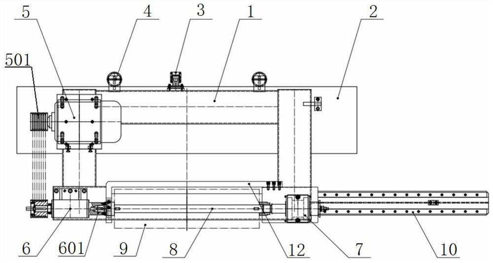
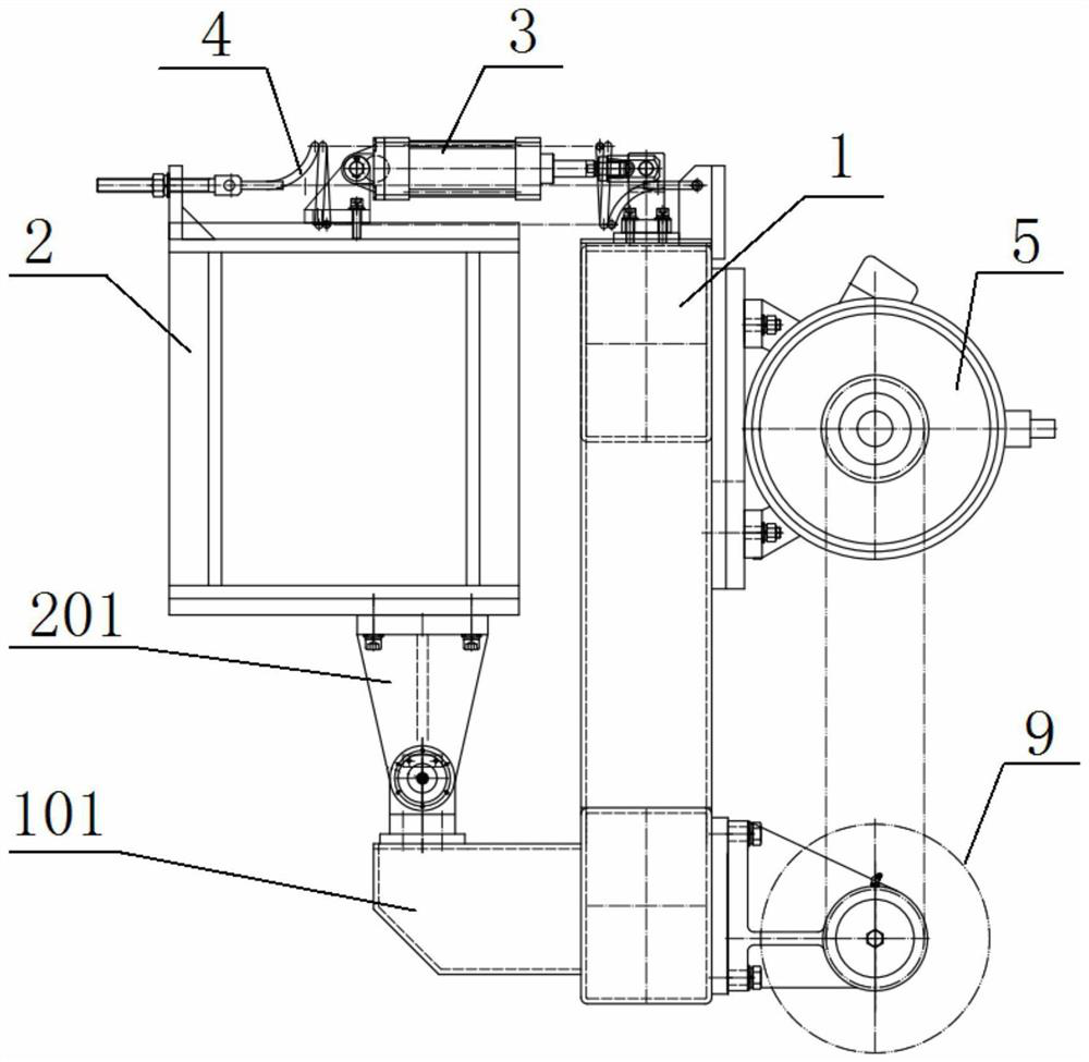
[0042] This embodiment discloses a compound grinding equipment for plate grinding, see figure 1 and figure 2 , including grinding head frame 1, beam 2, cylinder 3, two tension springs 4, drive motor 5, spindle seat mechanism 6, mandrel seat 7, mandrel 8, wire brush roller 9, slide rail assembly 10 and roller changing support Rack 12.

[0043] The grinding head frame 1 is a rectangular frame, and the grinding head frame 1 is vertically arranged, and a hinge shaft I101 protrudes laterally from the lower end thereof.

[0044] The beam 2 is spaced apart from the grinding head frame 1 . A hinge shaft II201 protrudes vertically from the lower end of the beam 2 . The hinge shaft II201 at the lower end of the beam 2 is hinged to the hinge shaft I101 of the grinding head frame 1 .

[0045] The upper end of the cylinder 3 is hinged on the upper end of the crossbeam 2, and the telescopic rod of the cylinder 3 is hinged on the upper end of the grinding head frame 1. Specifically, the...

Embodiment 2

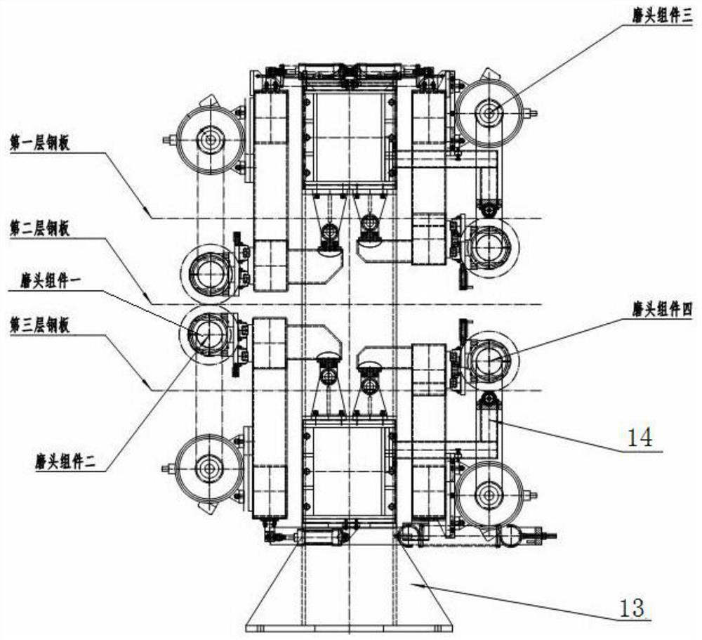
[0062] This embodiment provides a grinding head equipment composed of four grinding heads. In actual use, it is generally necessary to combine four grinding heads to achieve simultaneous rapid grinding of multi-layer plates. The lower ends of the four grinding heads Supported by the frame 13, the production efficiency can be greatly improved. When multiple grinding heads are used in combination, in order to ensure that as many surfaces as possible can be ground at the same time, the following steps can be followed: image 3 Install in the manner shown, the two wire brush rollers in the middle (grinding head assembly 1 and Component 4) needs to install the corresponding support wheel assembly 14; before the equipment starts to work, the three-layer plates need to be placed in an orderly manner as shown in the figure, and then the four grinding heads can be started at the same time, so that To realize the surface treatment of the four surfaces of the three-layer plate; in order...

Embodiment 3

[0064] This embodiment provides a relatively basic implementation method, a kind of plate grinding compound grinding equipment, see figure 1 and figure 2 , including grinding head frame 1, beam 2, cylinder 3, two tension springs 4, drive motor 5, spindle seat mechanism 6, mandrel seat 7, mandrel 8, wire brush roller 9, slide rail assembly 10 and roller changing support Rack 12.

[0065] The grinding head frame 1 is a rectangular frame, and the grinding head frame 1 is vertically arranged, and a hinge shaft I101 protrudes laterally from the lower end thereof.

[0066] The beam 2 is spaced apart from the grinding head frame 1 . A hinge shaft II201 protrudes vertically from the lower end of the beam 2 . The hinge shaft II201 at the lower end of the beam 2 is hinged to the hinge shaft I101 of the grinding head frame 1 .

[0067] The upper end of the cylinder 3 is hinged on the upper end of the crossbeam 2, and the telescopic rod of the cylinder 3 is hinged on the upper end of...


PUM


Abstract

The invention discloses grinding equipment for plate grinding compounding. The grinding equipment comprises a grinding head frame, a cross beam, an air cylinder, a plurality of tension springs, a driving motor, a main shaft seat mechanism, a core shaft seat, a core shaft, a steel wire brush roller and a sliding rail assembly. A hinge shaft II at the lower end of the cross beam is hinged to a hinge shaft I of the grinding head frame; the air cylinder is hinged at the upper end of the cross beam, and a telescopic rod of the air cylinder is hinged at the upper end of the grinding head frame. the driving motor is mounted at the upper end of the grinding head frame; the main shaft seat mechanism comprises a main shaft and a main shaft seat; the sliding rail assembly comprises a sliding plate and a sliding groove; the core shaft seat is mounted on the sliding plate; a rotatable shaft is installed in the core shaft seat, one end of the core shaft is connected to the main shaft, and the other end of the core shaft is connected to the rotating shaft; and the steel wire brush roller is sleeved with the core shaft, and connected with the core shaft into a whole by a locking nut. According to the grinding equipment, a workpiece is scraped and ground through high-speed rotational motion of the steel wire brush roller, the grinding quality is high, the production efficiency is high, and the grinding equipment can be used for surface treatment of large-area plates.

Description

technical field [0001] The invention belongs to the technical field of grinding machines, and in particular relates to a compound grinding equipment for plate grinding. Background technique [0002] At present, with the development of society, the application fields of composite materials continue to expand, the composite material industry has developed rapidly, and the demand for composite materials in all walks of life is also increasing. The old molding process is becoming more and more perfect, and new molding methods are emerging. Among them, the compression molding method is widely used. Before molding composite materials, it is often necessary to pre-surface the materials in order to produce composite materials that meet actual requirements. [0003] In order to meet the requirements of corrosion resistance, wear resistance, decoration or other special functions of products, surface treatment of these products is often required to clean, deburr, degrease, descale, et...

Claims


Application Information

Patent Timeline
IPC IPC(8): B24B41/047B24B27/00B24B55/06B24B7/12B24B47/12B24B47/06
CPCB24B7/12B24B27/0076B24B41/047B24B47/06B24B47/12B24B55/06
Inventor 黄云邹晓陈树林黄仟李平肖贵坚宋沙雨徐佳玉
Owner CHONGQING UNIV
Why Eureka
Try Eureka