Carton die-cutting machine

A die-cutting machine and carton technology, applied in papermaking, paper/cardboard containers, container manufacturing machinery, etc., can solve the problems of increasing storage space, affecting cutting work, and paper residues, and achieving the effect of improving the degree of automation

Inactive Publication Date: 2021-06-15
崔建文
View PDF1 Cites 2 Cited by
  • Summary
  • Abstract
  • Description
  • Claims
  • Application Information

AI Technical Summary

Problems solved by technology

[0006] Aiming at the deficiencies of the prior art, the present invention provides a carton die-cutting machine, which solves the problem that a large amount of paper remains on the surface of the conveying roller after the carton is cut by the die-cutting machine, which will affect the next cutting work. Increased storage space when storing knives in tool boxes

Method used


Image

  • Carton die-cutting machine
  • Carton die-cutting machine
  • Carton die-cutting machine

Examples


Embodiment 1

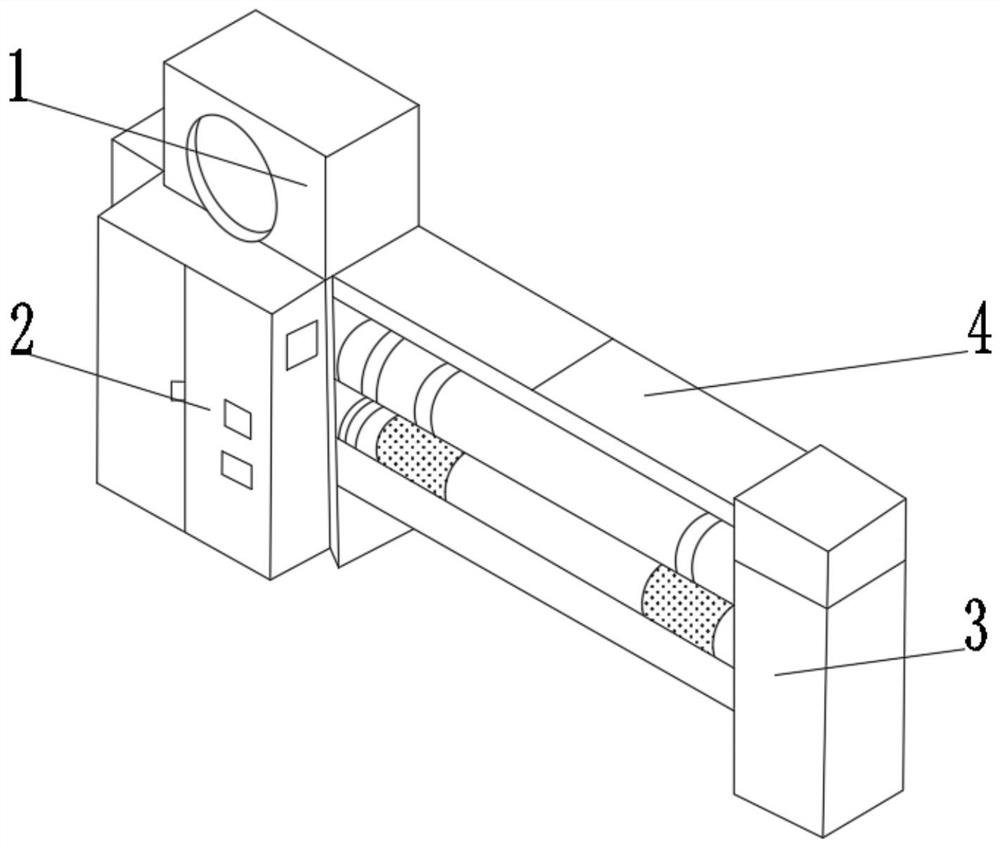
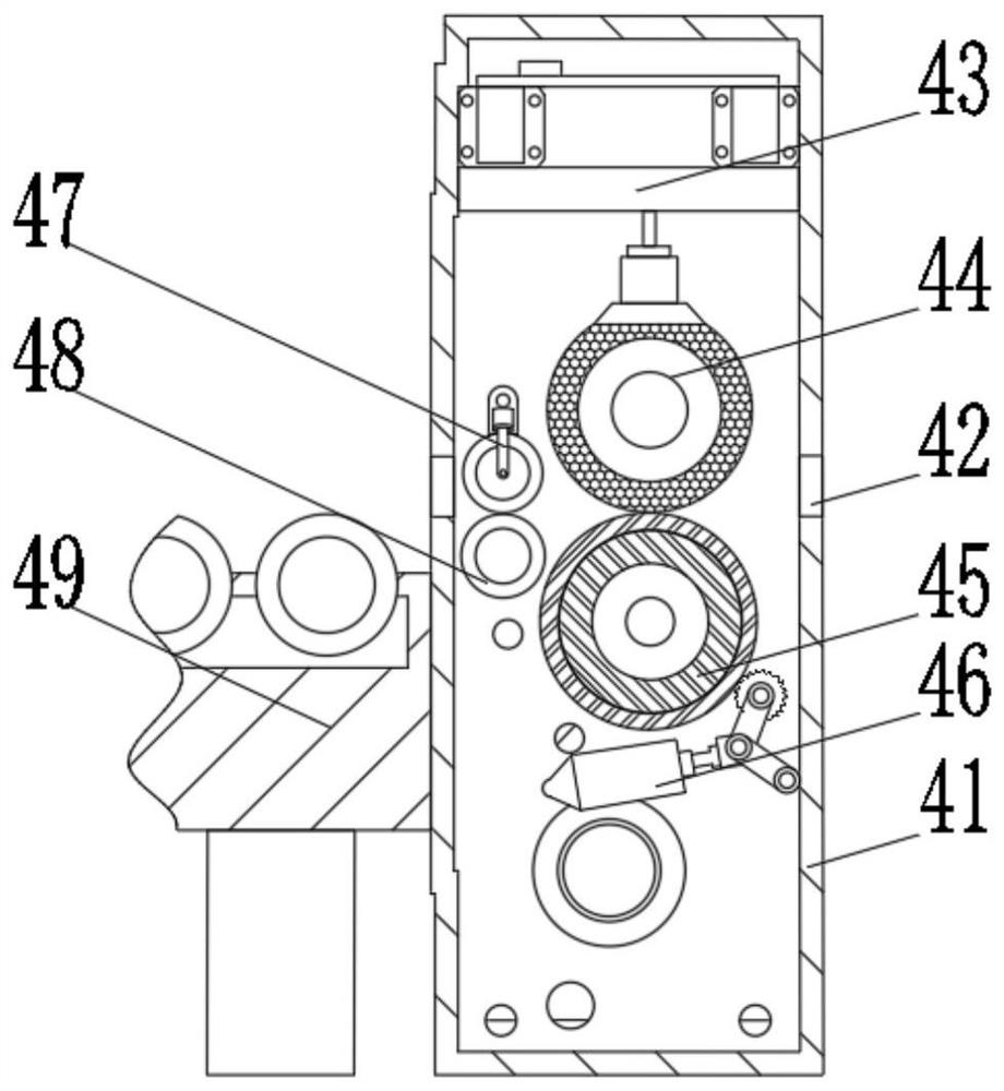
[0034] see Figure 1-2 , the present invention provides a technical solution: a carton die-cutting machine, including a die-cutting control box 1, a door panel 2 is arranged on one side of the die-cutting control box 1, and a fixed frame 3 is fixedly connected to one side of the die-cutting control box 1 , the inside of the fixed frame 3 is provided with a cutting mechanism 4, the cutting mechanism 4 includes a cutting and fixing shell 41, both sides of the cutting and fixing shell 41 are provided with feed ports 42, and the inner wall sides of the cutting and fixing shell 41 are fixedly connected with Fixed plate 43, one side of the fixed plate 43 is provided with a cutting device 44, the side of the cutting device 44 away from the fixed plate 43 is provided with a first motorized roller 45, and the side of the first motorized roller 45 away from the cutting device 44 is provided with a cleaning mechanism 46, the cutting and fixing casing 41 is provided with a pressure roller...

Embodiment 2

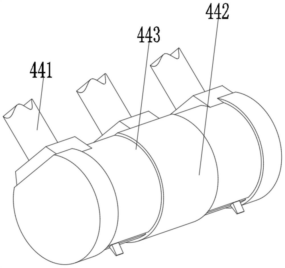
[0037] see Figure 2-5, the present invention provides a technical solution on the basis of Embodiment 1: a carton die-cutting machine, the cutting device 44 includes a telescopic rod 441, and one end of the telescopic rod 441 is fixedly connected with a connecting and fixing device 442, and the inner wall of the connecting and fixing device 442 The side is fixedly connected with a cutting rod 443, and the cutting rod 443 includes a cutting shell a1, and one side of the cutting shell a1 is provided with a mounting groove a2, and one side of the inner wall of the mounting groove a2 is fixedly connected with a blade cleaning device a3, and the cutting shell a1 The sides are fixedly connected with the guide rod a4 and the sliding connection housing a5, the inner wall side of the sliding connection housing a5 is fixedly connected with the electromagnetic block a6, and the side of the electromagnetic block a6 away from the sliding connection housing a5 is slidingly connected with th...

Embodiment 3

[0040] see Figure 4-6 , the present invention provides a technical solution on the basis of Embodiment 2: a carton die-cutting machine, the cutting knife seat a8 includes a knife seat shell a81, and one side of the knife seat shell a81 is provided with a connecting groove a82, and the connecting groove One side of a82 is provided with a limiting block a83, and the end of the limiting block a83 away from the connecting groove a82 is fixedly connected with a cutting blade a84, and the upper side of the cutting blade a84 close to the limiting block a83 is fixedly connected with a spring a85, and the spring a85 is away from One side of the cutting blade a84 is fixedly connected with the knife base housing a81, one end of the cutting blade a84 is rotationally connected with the knife base housing a81 through a rotating shaft, and the side of the knife base housing a81 close to the cutting blade a84 is fixedly connected with The arc-shaped limit rod a86, the side of the cutting bla...


PUM


Abstract

The invention discloses a carton die-cutting machine, and relates to the technical field of carton cutting. A fixed frame is fixedly connected to one side of a die cutting control box, a cutting mechanism is arranged inside the fixed frame, feeding ports are formed in two sides of a cutting fixing shell correspondingly, fixed plates are fixedly connected to the side faces of the inner walls of the cutting fixing shell correspondingly, a cutting device is arranged on one side of each fixed plates, a first electric roller is arranged on one side, away from the fixed plates, of the cutting device, a cleaning mechanism is arranged on one side, away from the cutting device, of the first electric roller, a pressing roller is arranged on one side, close to the cutting device, of the cutting fixing shell, a second electric roller is arranged below one side, close to the pressing roller, of the cutting fixing shell, a conveying device is arranged below one side, close to the second electric roller, of the feeding ports. According to the carton die-cutting machine, after equipment cuts a carton, a worker does not need to manually clean sweeps in the equipment, and after work, a cutting knife board is moved into a knife holder shell and does not need to be stored in a tool box, so that the storage space of a knife is reduced.

Description

technical field [0001] The invention relates to the technical field of carton cutting, in particular to a carton die-cutting machine. Background technique [0002] The automatic carton production machine is divided according to the type of cutter used or the type of cutting edge of the carton, mainly including serrated knives and flat knives. The knife with a straight edge, the edge (cutting edge) of the flat knife carton is flat but the cost is high, so it can only be applied to high-end gift box products, while the knife edge (cutting edge) of the serrated knife carton is relatively rough, so it is mainly used in low-end packaging. Boxes such as beer boxes, fruit boxes, cargo transfer boxes, etc. [0003] For example, Chinese patent CN103640055A discloses a carton continuous die-cutting machine, which includes two parallel conveying rollers. The conveying rollers are front-end conveying roller and rear-end conveying roller respectively, the top of the rear-end conveying ...

Claims


Application Information

Patent Timeline
Patent Type & Authority Applications(China)
IPC IPC(8): B31B50/20B31B50/04B31B50/00B31B50/74
CPCB31B50/006B31B50/042B31B50/142B31B50/20B31B50/74
Inventor 崔建文
Owner 崔建文
Why Eureka
Try Eureka