Hot blast stove for grain dryer

A technology for grain dryers and hot blast stoves, which is applied in the direction of dryers, drying, and drying gas arrangement. Full, heat-stable effect

Pending Publication Date: 2021-07-16
合肥三伍机械有限公司
View PDF0 Cites 0 Cited by
  • Summary
  • Abstract
  • Description
  • Claims
  • Application Information

AI Technical Summary

Problems solved by technology

[0003] At present, the working efficiency of the existing hot blast stove is low, and it is easy to cause a large amount of heat loss during the working process, and the hot air in the combustion chamber of the existing hot blast stove is not mixed uniformly, so that the discharged hot air cannot achieve the desired effect
[0004] Most of the hot blast stoves manually feed the fuel into the furnace body. Even if there is an automatic conveying device for the hot blast stove to realize automatic feeding, some biomass fuels are light in weight, and they are easy to float during the vertical feeding process and cannot be accurately dropped on the combustion plate. Complete combustion also brings more dust to the combustion pool
Some of the hot blast stoves in the prior art adopt a flat tube feeding method, which causes the biomass fuel to easily accumulate on the edge of the combustion chamber, and the combustion efficiency is low, and the biomass fuel is sometimes cut, crushed, etc. Screws and other small metal objects will be mixed in. During the conveying process through the screw feeder, it is easy to cause material jams, and in severe cases, the screw feeder will be directly damaged.
[0005] The hot blast stove currently used cannot stir and mix the cold air and hot air, resulting in uneven temperature of the mixed gas, and the filter screen for filtering the dust in the gas is easily blocked, which affects the normal flow of the gas

Method used


Image

  • Hot blast stove for grain dryer
  • Hot blast stove for grain dryer
  • Hot blast stove for grain dryer

Examples


Embodiment Construction

[0036] In order to make the purpose, technical solutions and advantages of the embodiments of the present invention more clear, the technical solutions in the embodiments of the present invention will be clearly and completely described below in conjunction with the accompanying drawings in the embodiments of the present invention. Obviously, the described embodiments It is a part of embodiments of the present invention, but not all embodiments. Based on the embodiments of the present invention, all other embodiments obtained by persons of ordinary skill in the art without making creative efforts belong to the protection scope of the present invention.

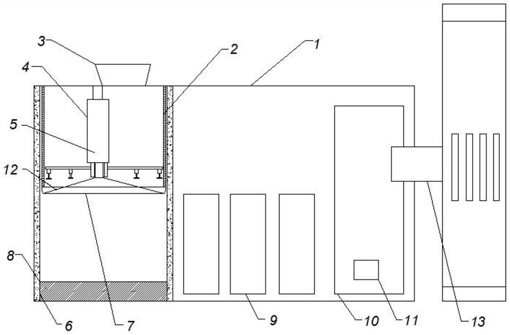
[0037] A hot blast stove for a grain dryer mainly includes a dryer mechanism and a hot blast stove mechanism, and the dryer mechanism and the hot blast stove mechanism are connected through a pipeline through a hot blast outlet 13;

[0038] Wherein, the interior of the hot blast stove mechanism includes a combustion chamber an...


PUM


Abstract

The invention discloses a hot blast stove for a grain dryer. The grain dryer communicates with the hot blast stove through a pipeline. The hot blast stove comprises a combustion chamber and a circulation chamber, the combustion chamber comprises a feeding device, a conveying device and a combustion device from top to bottom in sequence, and a settling chamber and a temperature control chamber are arranged in the circulation chamber. Through cooperative use of parts such as a transmission shaft, a cam, a mandrel, a support, an operating rod, a pressing plate, a spring and the like, the conveying device can accurately convey fuel in the vertical direction and also solves the problem that a spiral feeder is prone to material blocking; meanwhile, the pressing plate crushes granular biomass fuel, so that the granular biomass fuel can be combusted more sufficiently and are flammable; through cooperation of the feeding device, the conveying device, the combustion device and the circulation chamber, hot air in the combustion device is mixed with cold air after being subjected to multi-layer gravity dust removal, and the conveyed hot air is cleaner.

Description

technical field [0001] The invention belongs to the field of agricultural machinery manufacturing, in particular to a hot air stove for a grain dryer. Background technique [0002] The grain dryer is a type of dryer that dries grain, and the hot blast stove is an important component that provides heat for the dryer. When the grain dryer is working, the motor drives the impeller of the axial flow fan to rotate at a high speed, so that the hot air generated by the combustion of the coal furnace is sucked into the fan through the upper part of the baffle plate, and forms a mixture with the cold air sucked into the fan from the lower part of the baffle plate, and passes through the windshield pipe After entering the stacking rack, it diffuses. When the mixed gas passes through the grain layer on the stacking rack, the temperature of the millet is increased appropriately, and a large amount of water vapor is taken away to gradually dry the millet. [0003] At present, the workin...

Claims


Application Information

Patent Timeline
Patent Type & Authority Applications(China)
IPC IPC(8): F23K1/00F23K3/00B02C19/00B03C1/02F26B21/10
CPCB02C19/00B03C1/02F23K1/00F23K3/00F26B21/001F26B21/003F26B21/10
Inventor 张书宏叶新国张利
Owner 合肥三伍机械有限公司
Why Eureka
Try Eureka