Coiled tube type chemical reaction tank

A chemical reaction and reaction tank technology, which is applied in the field of coil type chemical reaction tanks, can solve the problems of wasting time for cleaning and replacement, slow reaction speed of reaction substances, and troublesome removal of agglomerated filter layers of reaction substances.

Pending Publication Date: 2021-09-14
高翌乔
View PDF0 Cites 0 Cited by
  • Summary
  • Abstract
  • Description
  • Claims
  • Application Information

AI Technical Summary

Problems solved by technology

[0002] The reaction tank has the characteristics of rapid heating, high temperature resistance, corrosion resistance, sanitation, no environmental pollution, automatic heating without boiler, easy to use, etc. It is widely used in petroleum, chemical, rubber, pesticide, dye, medicine, food, etc. Processes such as vulcanization, nitration, hydrogenation, alkylation, polymerization, and condensation are based on the premise of sufficient mixing of the reacting substances. For physical changes such as heating, cooling, liquid extraction, and gas absorption, stirring devices are required to obtain Good effect, the coiled tube reaction tank has the function of providing different temperature environments for the reaction substances according to needs; there are some problems in the use of the existing coiled tube chemical reaction tanks. First, the reaction materials in the reaction tank only rely on It is difficult for a group of stirring rods to stir quickly and evenly, so that the reaction speed of the reaction substance is slow, and it is troublesome to disassemble the filter layer of the reaction substance agglomeration in the discharge pipe, and it is extremely time-consuming to clean and replace. In order to solve the above problems, we propose a Coil type chemical reaction tank

Method used


Image

  • Coiled tube type chemical reaction tank
  • Coiled tube type chemical reaction tank
  • Coiled tube type chemical reaction tank

Examples


Embodiment Construction

[0022] In order to make the technical means, creative features, goals and effects achieved by the present invention easy to understand, the present invention will be further described below in conjunction with specific embodiments.

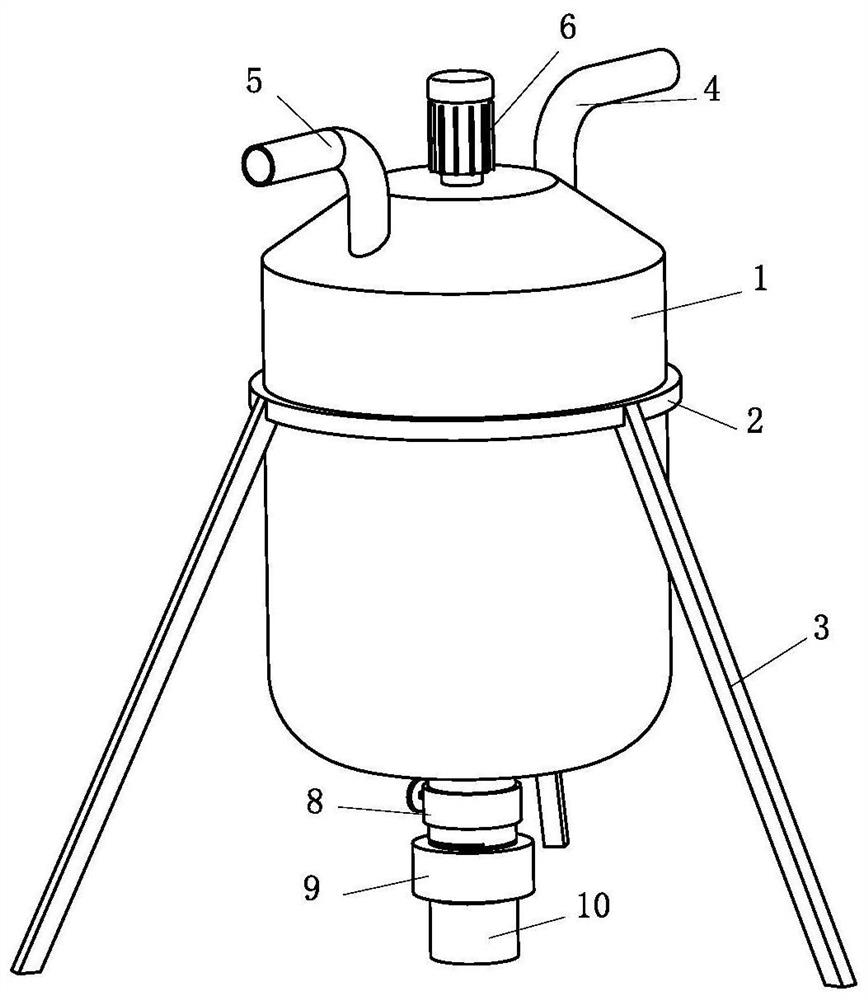
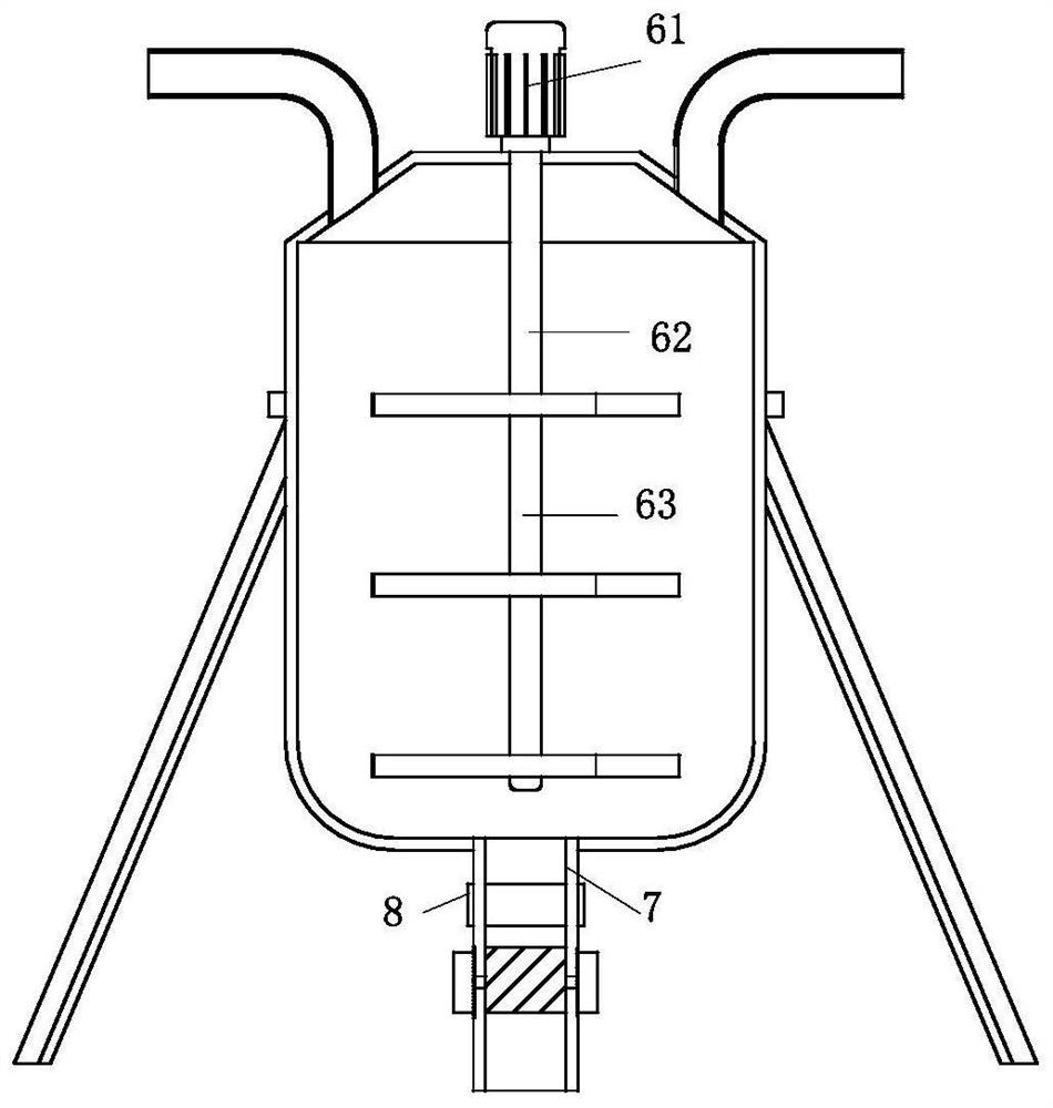
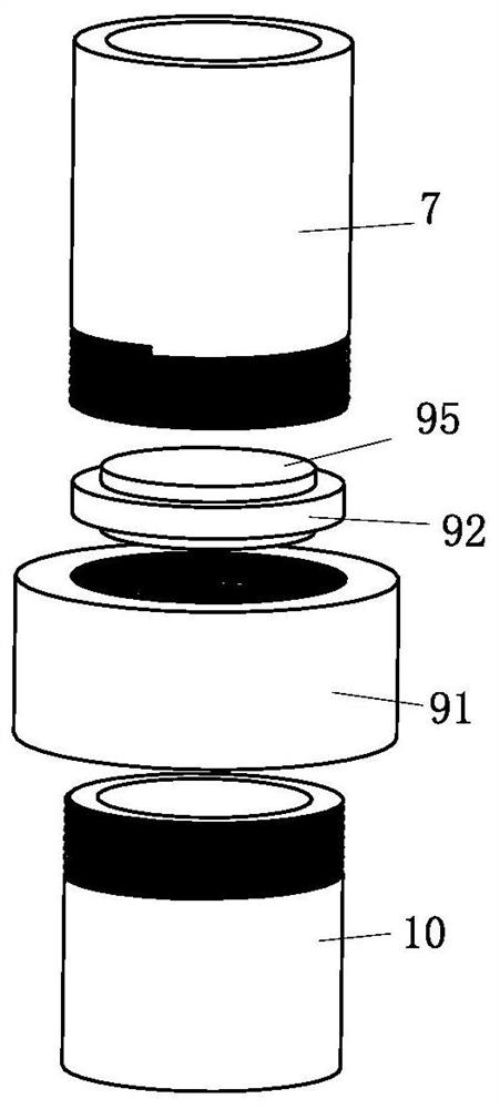
[0023] Such as Figure 1 to Figure 5 As shown, a coil type chemical reaction tank includes a reaction tank main body 1, the side of the reaction tank main body 1 is fixedly connected with a fixing hoop 2, the lower side of the fixing hoop 2 is fixedly connected with a support foot 3, and the upper end of the reaction tank main body 1 One side is fixedly connected with the first feeding pipe 4, the other side of the upper end of the reaction tank main body 1 is fixedly connected with the second feeding pipe 5, and the center of the upper end of the reaction tank main body 1 is provided with a stirring mechanism 6, and the stirring mechanism 6 includes a motor 61, the lower end of the motor 61 is provided with a rotating shaft 62, the lower part of ...


PUM


Abstract

The invention relates to the technical field of chemical reaction tanks, and concretely relates to a coiled tube type chemical reaction tank. The reaction tank comprises a reaction tank main body, a fixing hoop is fixedly connected to the side face of the reaction tank main body, supporting legs are fixedly connected to the lower side of the fixing hoop, and a first feeding pipe is fixedly connected to one side of the upper end of the reaction tank main body. A second feeding pipe is fixedly connected to the other side of the upper end of the reaction tank main body, a stirring mechanism is arranged in the center of the upper end of the reaction tank main body and comprises a motor, a rotating shaft is arranged at the lower end of the motor, a shifting plate is fixedly connected to the lower part of the rotating shaft, and a discharging pipe is fixedly connected to the lower end of the reaction tank main body. According to the coiled tube type chemical reaction tank disclosed by the invention, reaction substances in the reaction tank main body can be uniformly stirred from top to bottom through the three groups of stirring plates, so that the reaction substances are relatively quickly and uniformly stirred, the reaction substances can be relatively fully reacted, and the filtering layer can be conveniently and quickly cleaned or replaced.

Description

technical field [0001] The invention relates to the technical field of chemical reaction tanks, in particular to a coil type chemical reaction tank. Background technique [0002] The reaction tank has the characteristics of rapid heating, high temperature resistance, corrosion resistance, sanitation, no environmental pollution, automatic heating without boiler, easy to use, etc. It is widely used in petroleum, chemical, rubber, pesticide, dye, medicine, food, etc. Processes such as vulcanization, nitration, hydrogenation, alkylation, polymerization, and condensation are based on the premise of sufficient mixing of the reacting substances. For physical changes such as heating, cooling, liquid extraction, and gas absorption, stirring devices are required to obtain Good effect, the coiled tube reaction tank has the function of providing different temperature environments for the reaction substances according to needs; there are some problems in the use of the existing coiled tu...

Claims


Application Information

Patent Timeline
IPC IPC(8): B01J19/00B01J19/18B01J4/00B01D35/02
CPCB01J19/0066B01J19/18B01J4/001B01D35/02B01J2204/005
Inventor 高翌乔张贤
Owner 高翌乔
Why Eureka
Try Eureka