Well drilling device for oil exploitation

A drilling and oil technology, which is applied in the field of drilling equipment for oil development, can solve the problems of adjustment, inability to stabilize and quickly drive the height of components, and achieve the effects of improving stability, convenient and quick disassembly and connection, and stable height adjustment.

Inactive Publication Date: 2021-09-17
王飞
View PDF0 Cites 1 Cited by
  • Summary
  • Abstract
  • Description
  • Claims
  • Application Information

AI Technical Summary

Problems solved by technology

[0009] The purpose of the present invention is to provide a drilling device for oil exploitation to solve the problem in the above-mentioned background technology that the height of the driving assembly cannot be adjusted stably and quickly

Method used


Image

  • Well drilling device for oil exploitation
  • Well drilling device for oil exploitation
  • Well drilling device for oil exploitation

Examples


Embodiment 1

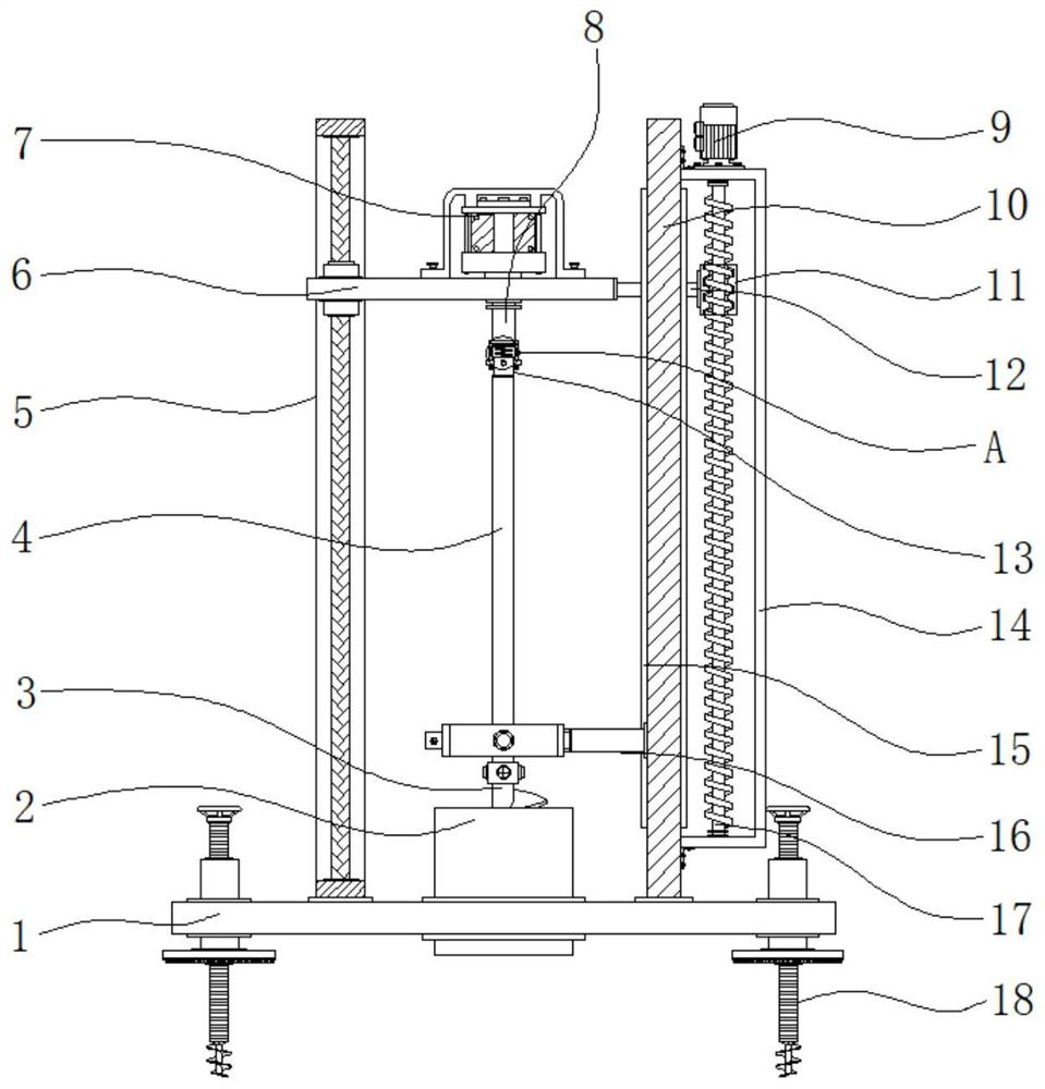
[0035] Example 1: see Figure 1-6 , a drilling device for oil exploitation, comprising a bottom plate 1, a cylinder 2 is inserted at the middle position of the top of the bottom plate 1, a fixed vertical plate 10 is fixedly connected to one side of the top of the bottom plate 1, and the top of one side of the fixed vertical plate 10 is provided with There is a top plate 6, one side of the top of the top plate 6 is fixedly connected with a drive motor 7, the model of this drive motor 7 can be Y90S-2, the output end of the drive motor 7 is fixedly connected with a drive shaft 8, and the bottom end of the drive shaft 8 penetrates the top plate. 6. The other side of the top of the bottom plate 1 is provided with a stabilizing structure 5, the bottom end of the drive shaft 8 is provided with a drill rod 4, the bottom end of the drill rod 4 is fixedly connected with a drill bit 3 through a coupling, and the bottom end of the drive shaft 8 and A dismounting structure 13 is arranged bet...

Embodiment 2

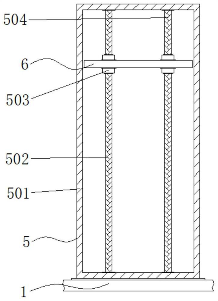
[0039] Embodiment 2: The stabilizing structure 5 is composed of a fixed frame 501, a first stabilizing column 502, a sliding sleeve 503 and a second stabilizing column 504. The fixing frame 501 is fixedly connected to the other side of the top of the bottom plate 1, and the inner ends of the fixing frame 501 are between two ends. The front end of the frame 501 is fixedly connected to the second stabilizing column 504, the rear end between the two inner ends of the fixed frame 501 is fixedly connected to the first stabilizing column 502, and the sliding sleeves 503 are respectively inserted at the two ends of the other side of the top of the top plate 6;

[0040] The first stabilizing column 502 and the second stabilizing column 504 penetrate through the inside of the sliding sleeve 503 respectively, and a sliding structure is formed between the first stabilizing column 502 and the second stabilizing column 504 and the sliding sleeve 503 respectively;

[0041] Specifically, as ...

Embodiment 3

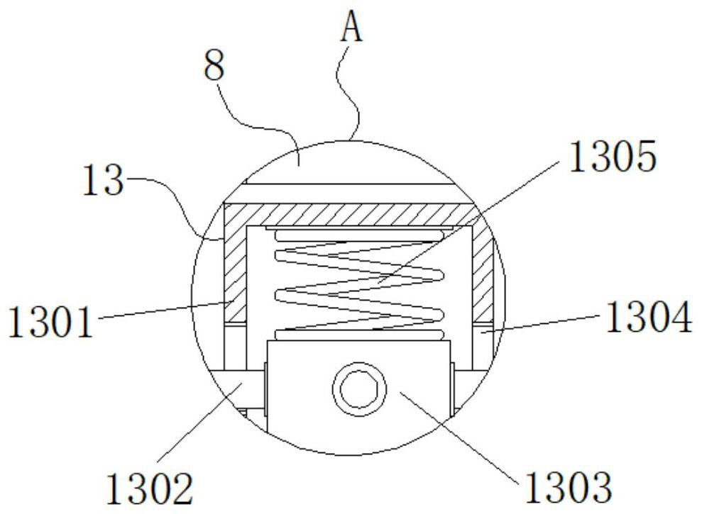
[0042] Embodiment 3: The disassembly structure 13 is composed of an installation groove 1301, a clamping rod 1302, an installation block 1303, a clamping groove 1304 and a compression spring 1305. The installation groove 1301 is fixedly connected to the bottom end of the drive shaft 8, and the installation block 1303 is fixedly connected to the drill. At the top of the rod 4, the outside of the installation groove 1301 is evenly provided with a clamping groove 1304, the outside of the installation block 1303 is evenly fixedly connected with a clamping rod 1302, and the top of the inside of the installation groove 1301 is fixedly connected with a compression spring 1305;

[0043] The clamping rod 1302 is provided with four groups, and the outside of the mounting block 1303 of the clamping rod 1302 is annularly distributed;

[0044] The clamping rods 1302 are respectively embedded in the interior of the clamping grooves 1304, and a clamping structure is formed between the clampin...


PUM


Abstract

The invention discloses a well drilling device for oil exploitation, and particularly relates to the technical field of oil exploitation. The well drilling device for oil exploitation comprises a bottom plate, wherein a barrel is inserted in the middle of the top end of the bottom plate, one side of the top end of the bottom plate is fixedly connected with a fixed vertical plate, and the top of one side of the fixed vertical plate is provided with a top plate. According to the well drilling device for oil exploitation, through the arrangement of a dismounting structure between the bottom end of a driving shaft and the top end of a drilling rod, when the drilling rod needs to be connected and lengthened during use, a mounting block fixedly connected with the top end of the drilling rod is inserted into a mounting groove fixedly connected to the bottom end of the driving shaft; a clamping rod fixedly connected to the outer part of the mounting block is clamped into a clamping groove through a specific bayonet, the mounting groove and the mounting block are fixedly connected through a clamping structure formed between the clamping rod and the clamping groove, and the mounting block is tightly abutted through the elastic force of a compression spring fixedly connected to the top end in the mounting groove, so that connection is firmer, and therefore, the purpose that the drilling rod can be conveniently and rapidly detached and connected is achieved.

Description

technical field [0001] The invention relates to the technical field of petroleum exploitation, in particular to a drilling device for petroleum exploitation. Background technique [0002] Oil is one of the most widely used non-renewable energy sources in today's society. Oil plays an important role in the development of industry. However, because oil is usually stored at a deeper depth below the surface, it is not convenient for exploration and exploitation. Drilling equipment is required for oil resources. For surveying and exploitation, the oil exploitation drilling device effectively improves the oil exploitation efficiency and reduces the oil exploitation cost, but there are still some defects in the actual use of the existing oil exploitation drilling device. [0003] In the process of realizing the present invention, the inventor found that at least the following problems have not been solved in the prior art: [0004] (1) The traditional oil drilling device cannot ad...

Claims


Application Information

Patent Timeline
Patent Type & Authority Applications(China)
IPC IPC(8): E21B15/00F16F15/067E21B17/10E21B3/02
CPCE21B15/00E21B15/006F16F15/067E21B17/10E21B3/022
Inventor 王飞
Owner 王飞
Why Eureka
Try Eureka